Popular Keywords

MIPI SoundWire

SoundWire, a hardware interface and transport protocol crafted by MIPI, serves as a versatile solution for seamless communication in audio systems. Engineered for efficiency, it boasts a straightforward design, low-power consumption, and minimal latency. Operating on a dual-lead (clock and data) bus, SoundWire facilitates the transfer of multiple audio streams, accommodating devices like amplifiers and microphones. Beyond its audio capabilities, it also supports embedded control commands. With a maximum clock rate of 12.288MHz, SoundWire ensures a reliable and expandable platform for diverse audio applications.

Application: Amplifier, microphone and audio encoder for smartphones, tablets and other devices.

Logic Analyzer

MSO2000 series Specifications PDF

MIPI SoundWire Decode
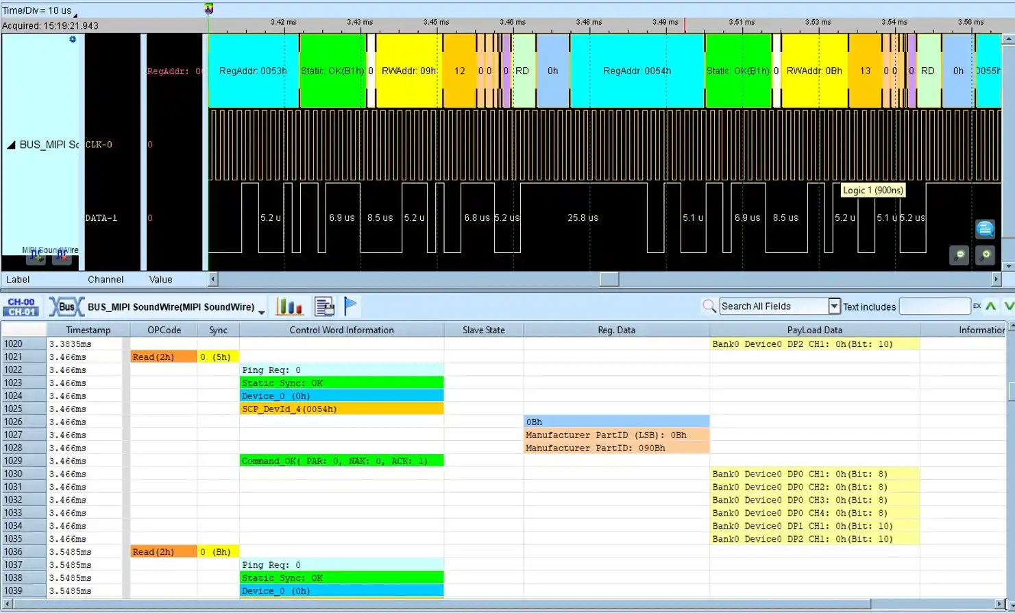
Control Word + Report (Control Word & Payload)

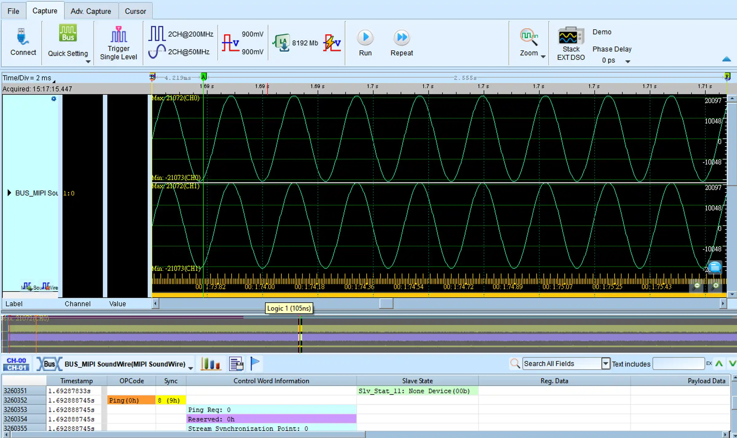
Audio Display + Report (Control Word & Payload)
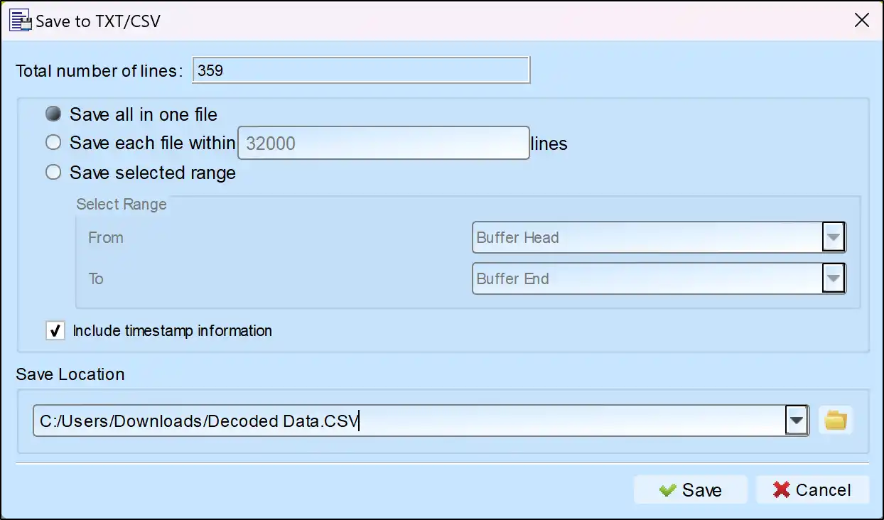
Save as TXT/CSV

In Logic Analyzer mode, click the icon above the report area to save the decoded data as a TXT/CSV file.

Export Icon

MIPI SoundWire Decoding Setup Steps

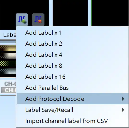
1. Click Quick Settings or Add Protocol Decode to select a protocol for logic analyzer capture.

2. Select MIPI SoundWire for decoding.

3. If you use Quick Settings, the system will recommend configurations for trigger type, sampling rate, voltage threshold, and channel settings.

4. Click the icon to access the Decode Settings screen.

Image 1
Image 2

Decode Settings

CLK: Clock signal

Data: Data signal 

Range: Analysis Range

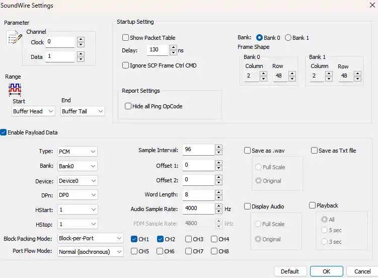
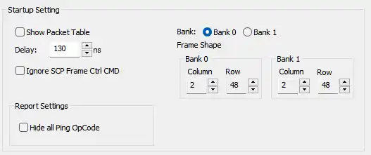
Show Packet Table: Show the Frame Data in report.

Delay: Set up time value

Ignore SCP Frame Ctrl CMD: SCP Frame won’t change

Hide all Ping OpCode: Hide the Ping Opcode frame data.

Bank: Select Bank for parameter

Frame Shape: Input Column & Row (Bank 0 & 1)


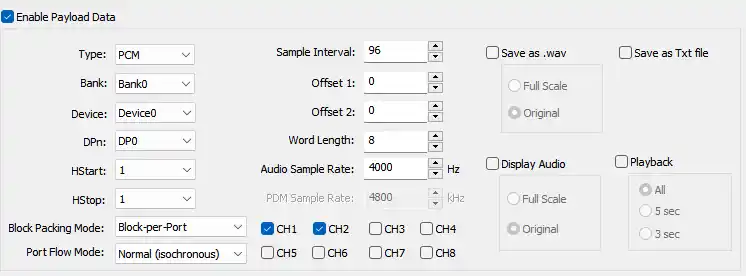
Enable Payload Data: Enable to Import & Display Payload settings

Type: Select audio format

Bank: Select bank

Device: Select Device

DPn: Select Data Port

PDM Sample Rate: PDM data sample rate per bit

Audio Frequence: PCM audio frequence

Display: Draw the audio wave

Playback: Play the selected audio

A Data Port is a subset of a Device that is either a source or sink of one Payload Stream on the SoundWire bus. Data Ports provide an abstraction of a Payload Stream being divided into one or more channels which, in the audio application space will correspond to individual audio channels.

1. Bank: 0~1

2. Device Number: 0~11

3. Data Port: DP0~DP15

4. HStart: HStart is a 4-bit number identifying the lowest numbered column in the SoundWire Frame that contains BitSlots for this Payload Stream.

5. HStop: HStop is a 4-bit number identifying the highest numbered column in the SoundWire Frame that might contain BitSlots for this Payload Stream.

6. Word Length: WordLength is a 6-bit number that controls the size of a Payload Channel Sample.

7. Sample Interval: Sample Interval is an integer in the range 2 to 65535 that controls the spacing from one Sample Event to the next, and the size of a Sample Window.

8. Block Package Mode:

 Block per port: Block Offset = Offset1 + (256 * Offset2)

 Block per channel: Block Offset = Offset1, Sub-Block Offset = Offset2.

 *Block Offset is an integer in the range 0 ~ 65535

 *Sub-Block Offset is an integer in the range 0 to 255

 *Offset1 is an integer in the range 0~65535

 *Offset2 is an integer in the range 0~255

9. Channel: Divide a Data Port into different parts, which are often used for data distribution of left and right audio channel etc. It can select up to 8 channels, and can be selected without order. (Input Format: 0xFF or 25510)

10. Port Flow Mode: Isochronous, Tx-Controlled, Rx-Controlled and Full-Asynchronous modes

 *Isochronous: ‘Normal’ mode No Valid data is transported in every Payload Data Block.

 *Tx-Controlled: ‘Push’ mode,A flow-control bit driven by the Source Data Port controls whether or not valid data is transported in the Payload Data Block.

 *Rx-Controlled: ‘Pull’ mode,A flow-control bit driven by the Sink Data Port controls whether or not valid data is transported in the Payload Data Block.

 *Full-Asynchronous: Flow-control bits driven by both the Source and Sink Data Ports control whether or not valid data is transported in the Payload Data Block.

11. Audio settings:

 a. Save as Wav: Save the audio data to .wav format. (It will be saved in your working directory.)

  1: Save audio data in wav format

  0: Only display data in hex in the report.

 b. Audio Type: PDM & PCM format supported.

 c. Audio Sample Rate: This is the audio sample rate for the PCM. (Unit: Hz)

 d. PDM Sample Rate: This is the parameter for PDM to PCM calculation. (Unit: Hz)

We use cookies to elevate your user experience and enhance the quality of our site. To find out more or adjust cookie settings, click here .