MII / RMII / RGMII / GMII

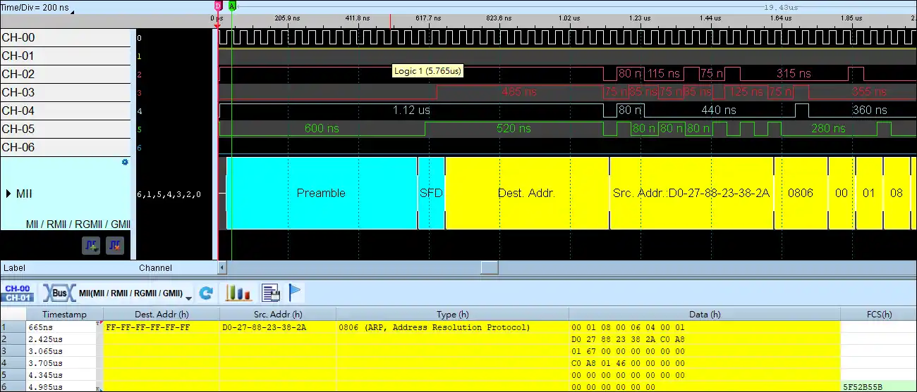
MII Decode
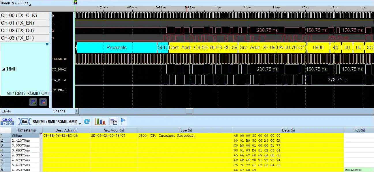
RMII Decode
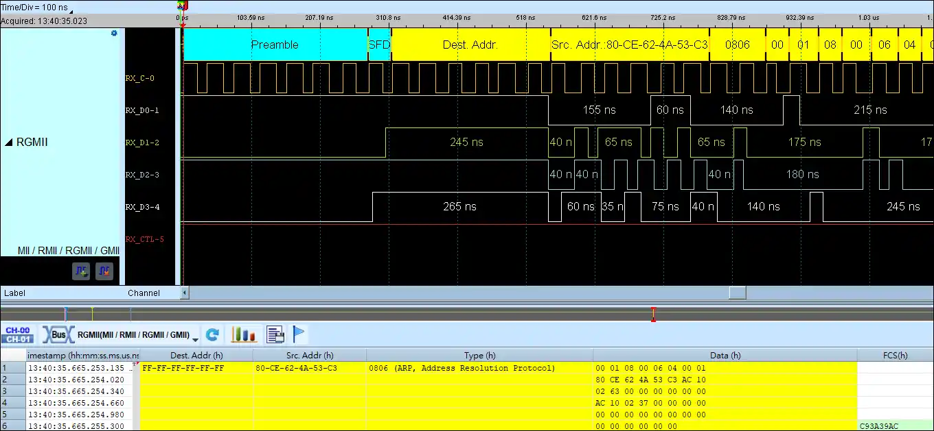
RGMII Decode
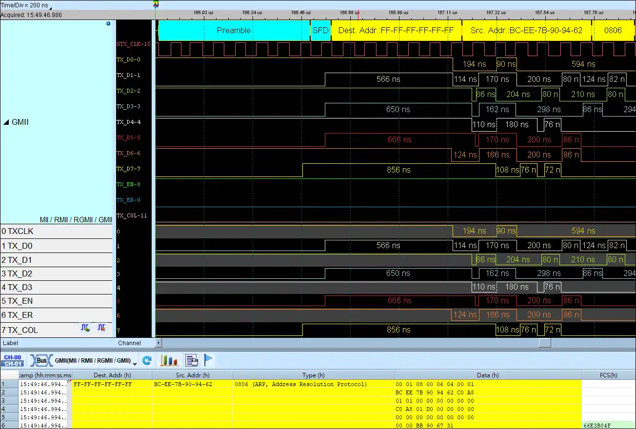
GMII Decode
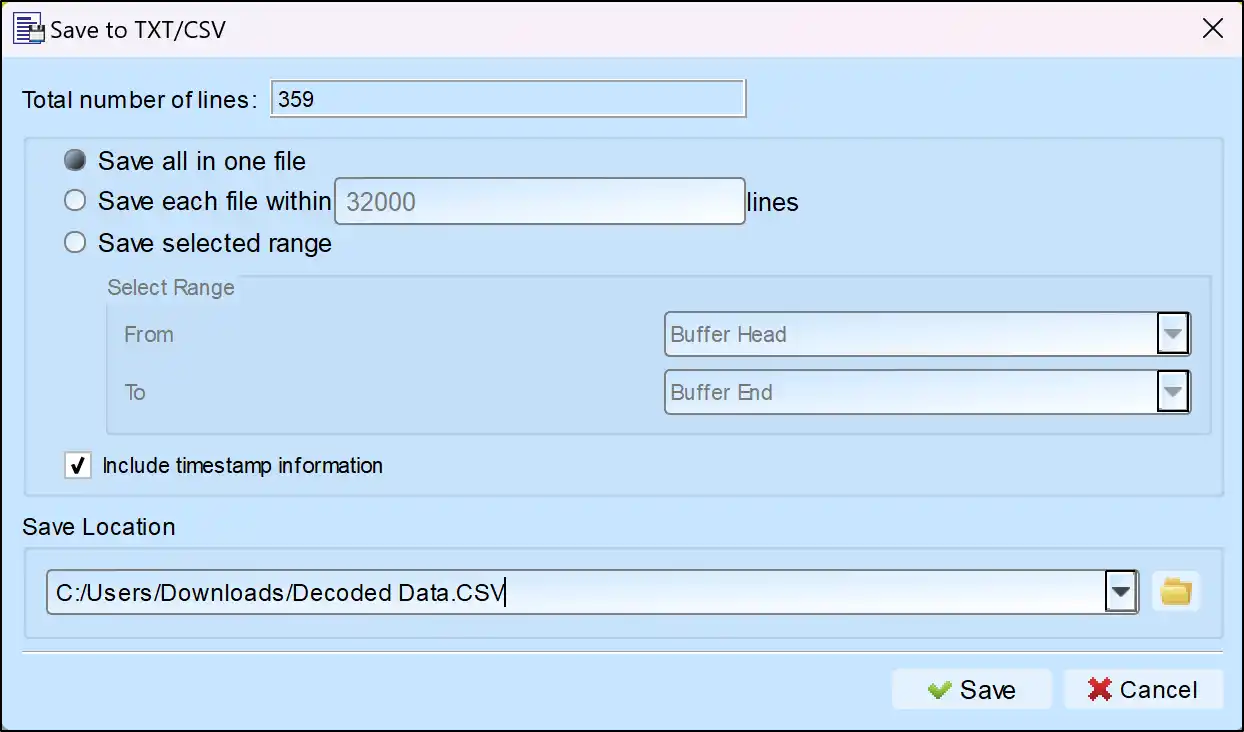
Save as TXT/CSV
In Logic Analyzer mode, click the icon above the report area to save the decoded data as a TXT/CSV file.

MII / RMII / RGMII / GMII Decoding Setup Steps
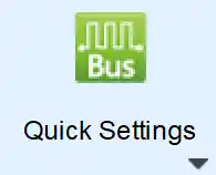
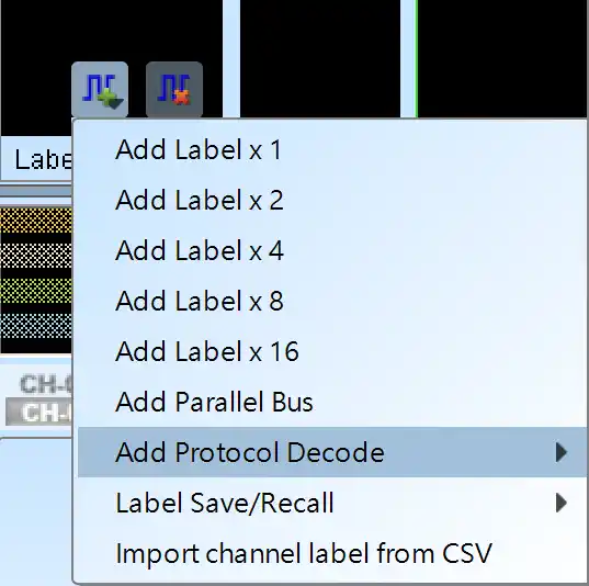
1. Click Quick Settings or Add Protocol Decode to select a protocol for logic analyzer capture.
2. Select MII / RMII / RGMII / GMII for decoding.
3. If you use Quick Settings, the system will recommend configurations for trigger type, sampling rate, voltage threshold, and channel settings.
4. Click the icon to access the Decode Settings screen.

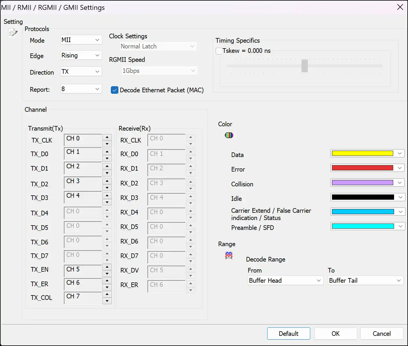
Decode Settings
MII / RMII: Select the MII / RMII bus decode
GMII / RGMII: Select the GMII / RGMII bus decode
Only CLK and Data pins used(M/G): Select MII / GMII the CLK and Data pins only.
Transmit (Tx): Select TX mode
Receive (Rx): Select Rx mode
Duplex (Tx+Rx) : Select duplex mode
Channel: Set the channel number.
Rising: Select rising edge to latch data
Falling: Select falling edge to latch data
8 columns: show 8 columns data field in the report window
16 columns: show 16 columns data field in the report window
MII Decoding Examples