QSPI

QSPI Decode
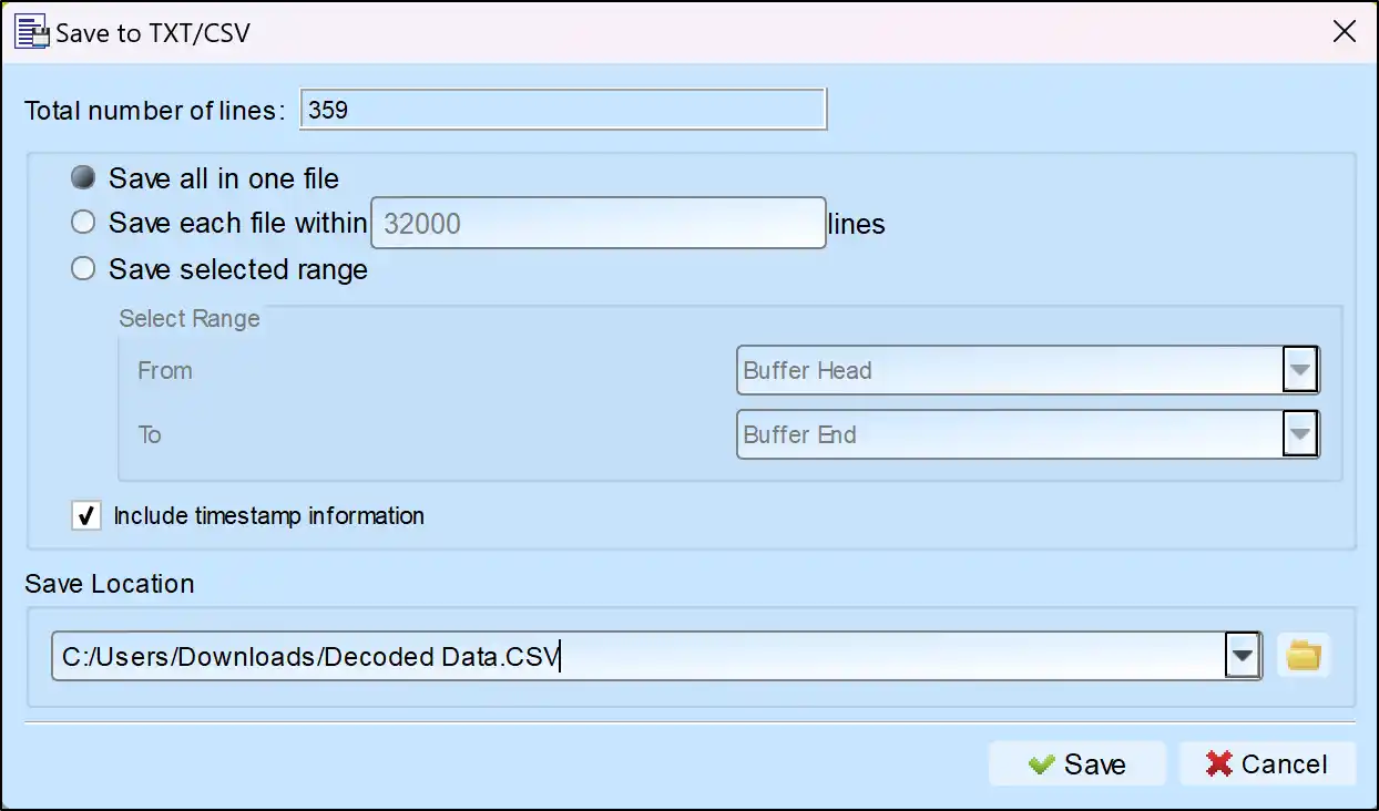
Save as TXT/CSV
In Logic Analyzer mode, click the icon above the report area to save the decoded data as a TXT/CSV file.

QSPI Decoding Setup Steps
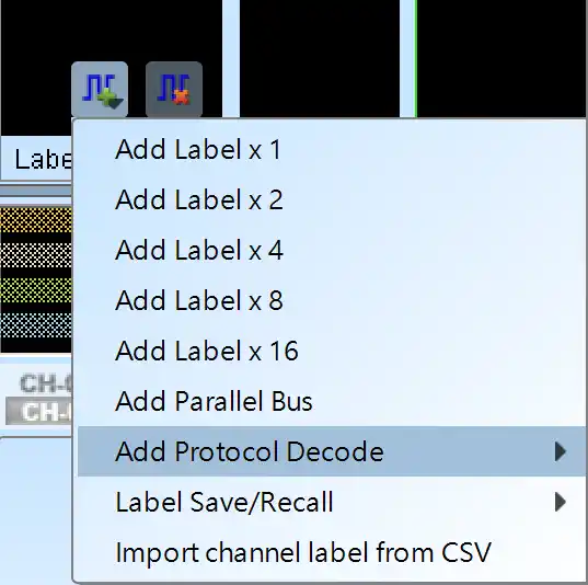
1. Click Quick Settings or Add Protocol Decode to select a protocol for logic analyzer capture.
2. Select QSPI for decoding.
3. If you use Quick Settings, the system will recommend configurations for trigger type, sampling rate, voltage threshold, and channel settings.
4. Click the icon to access the Decode Settings screen.

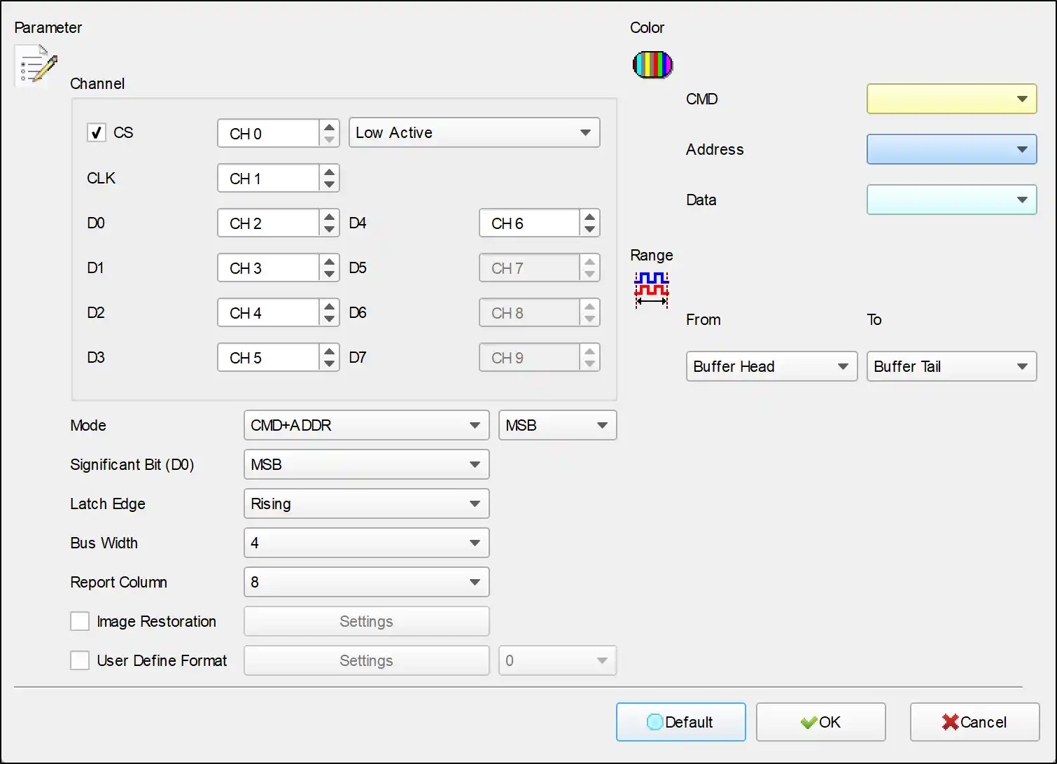
QSPI Decode Settings
Channel:
CS: Capture data when CS edge is falling.
CLK: Clock channel.
D0-D7: Customizable data channel.
Significant Bit(D0): D0 is the MSB or LSB of the data arrangement,
- Take Bus Width = 4 MSB as an example, the Byte combination is
D0 D1 D2 D3 D0 D1 D2 D3 - Take Bus Width = 4 LSB as an example, the Byte combination is
D3 D2 D1 D0 D3 D2 D1 D0
Latch Edge: Rising/Falling/Both can be selected as the data collection location.
Bus Width: Optional data 1, 2, 4, 8 lines.
Report Column: Report presentation mode, 8/16 fields can be selected.
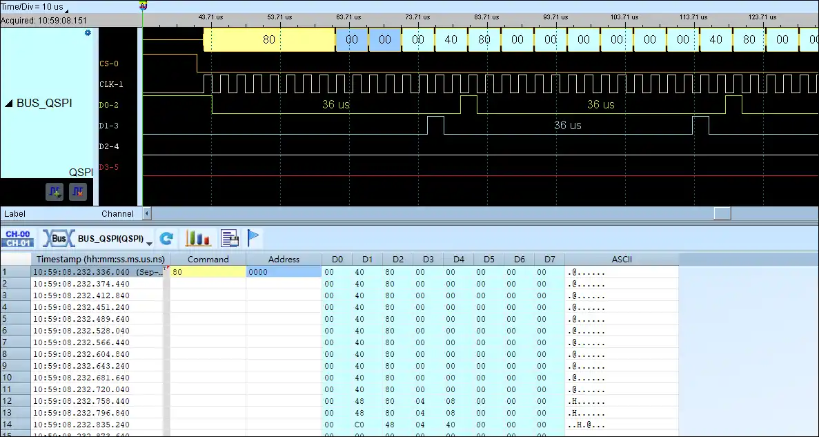
QSPI Decoding Example