Popular Keywords

MSO3124V Mixed Signal Oscilloscope

MSO3000 Mixed Signal Oscillosc

6-in-1 Instruments:
DAQ, DSO, DVM, Frequency Counter, Logic Analyzer, Protocol Analyzer
• PC-based, USB3.0 interface / powered (Type-A / Type-C)
• Total Memory:4 Gb
• Data Logger (HDD / SSD Storage)
• DSO:4 Channels, 1 GS/s S/R, 200 MHz bandwidth
• Digital Voltmeter :3 digits
• Frequency Counter:5 digits
• Logic / Protocol Analyzer:16 Channels, 2 GS/s Timing Analysis, 250 MHz State Analysis

Related Products

MSO3124V is a versatile 6-in-1 instrument that offers oscilloscope, logic analyzer, protocol analyzer, data collector, digital multimeter, and frequency counter functionalities. It can simultaneously measure and display both analog and digital signals. Due to its combination of multiple measurement and analysis capabilities, it is suitable for various application fields, from data collection to waveform analysis, allowing for efficient and accurate tasks.

MSO3124V oscilloscope features 4 channels, a 1 GS/s sampling rate, and a 200 MHz bandwidth, with a record length of 128Mpts for each channel. Additionally, it includes a 3-digit digital multimeter and a 5-digit frequency counter. The MSO3124V not only supports oscilloscope mode but also includes logic analyzer mode and protocol analyzer mode, making it suitable for different signal and bus analysis requirements.

In addition to its 16-bit high-resolution and oscilloscope stacking features, the MSO3124V also supports critical power management-related signals, such as Intel"s SVID and AMD"s SVI3. This makes the MSO3124V an ideal choice for handling modern power management and electrical characteristics verification.

DSO Functions:

Protocol Electrical Validation
This function will allow you to set up a decode & electrical validation parameter such as voltage, frequency, timing and etc. Then, the software will show all the testing results including the waveform, reference point and it can also create the testing report automatically.

In general settings, you can specify important parameters such as the signal source, operating voltage, and speed, among others. Additionally, decoding settings aid in a more in-depth signal analysis, and electrical verification allows for numerical range setting of verification items like voltage, timing, and frequency. On the software side, compliance with the specified parameters can be determined, ensuring the accuracy and stability of electronic devices.

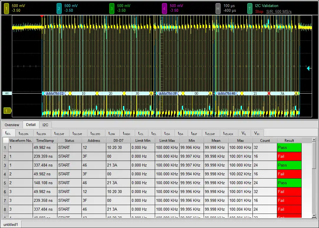
Software Test Report

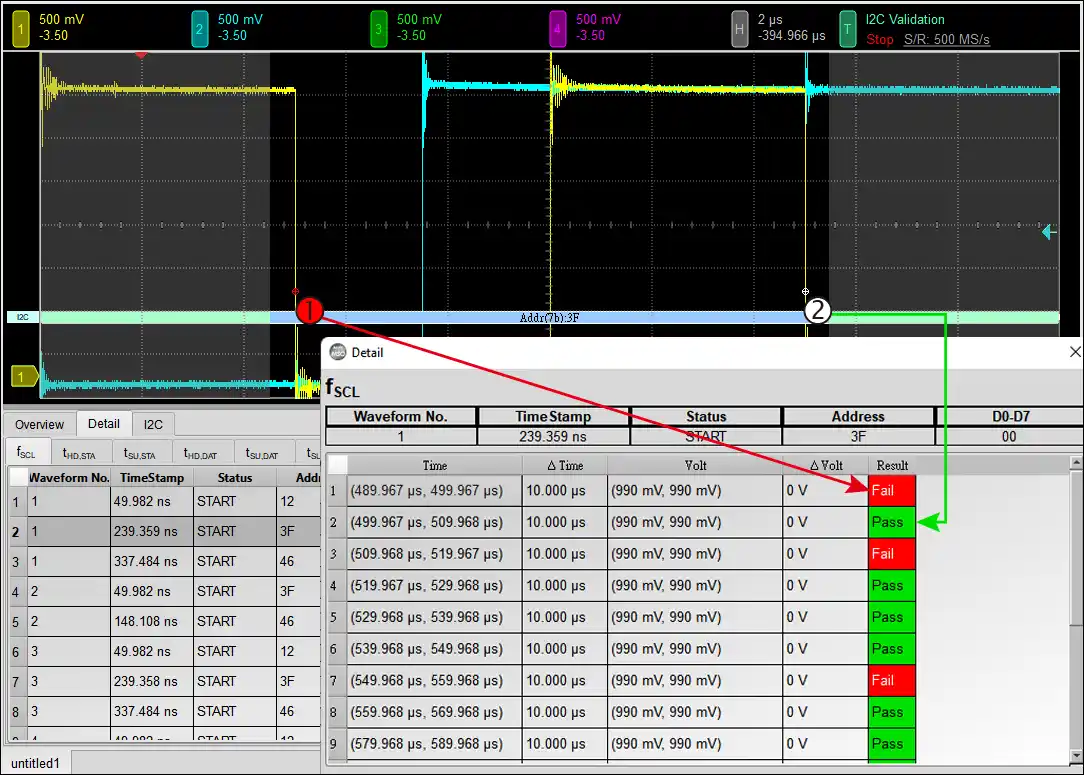
Reference Point Dialog & Waveform

HTML Report

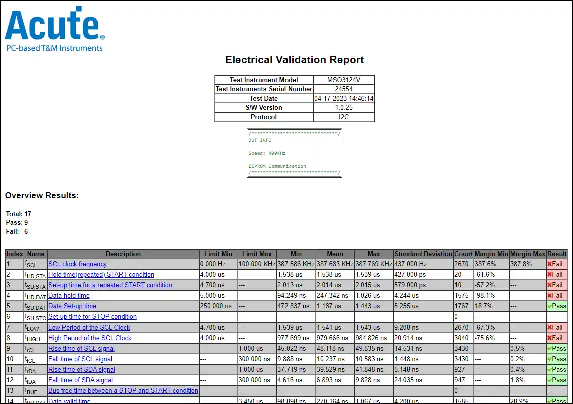
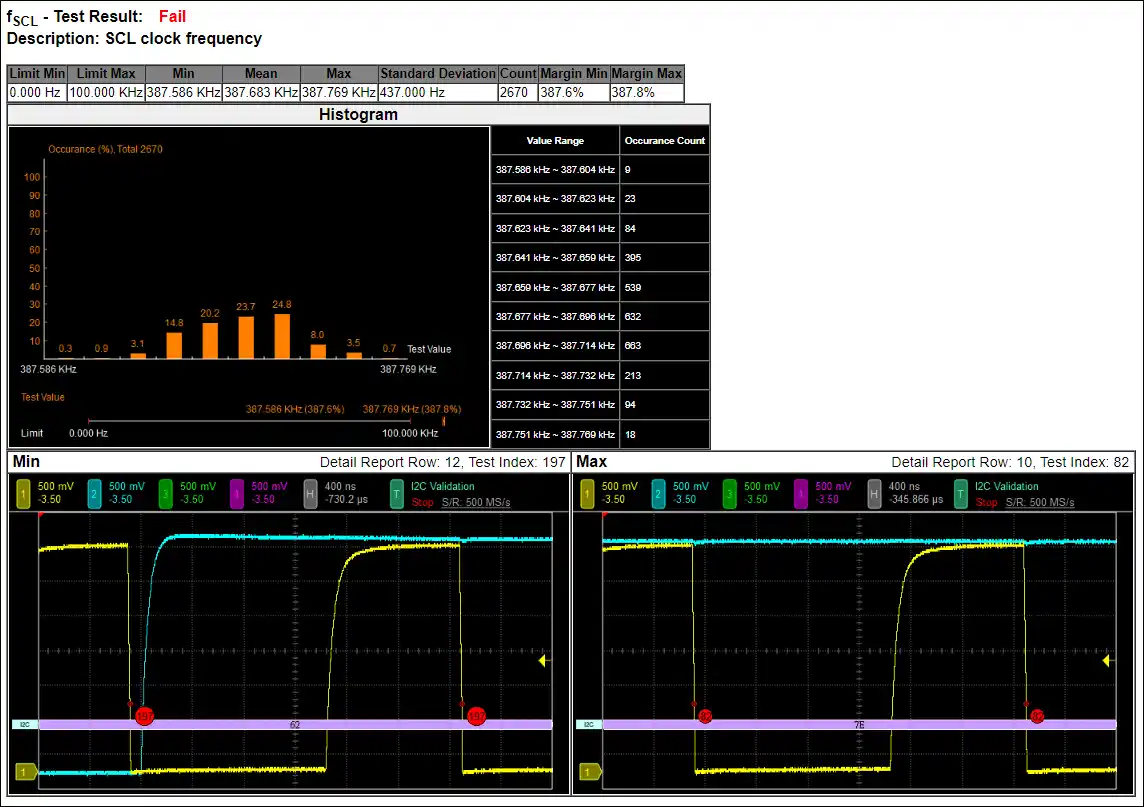
Detailed Contents of the HTML Report

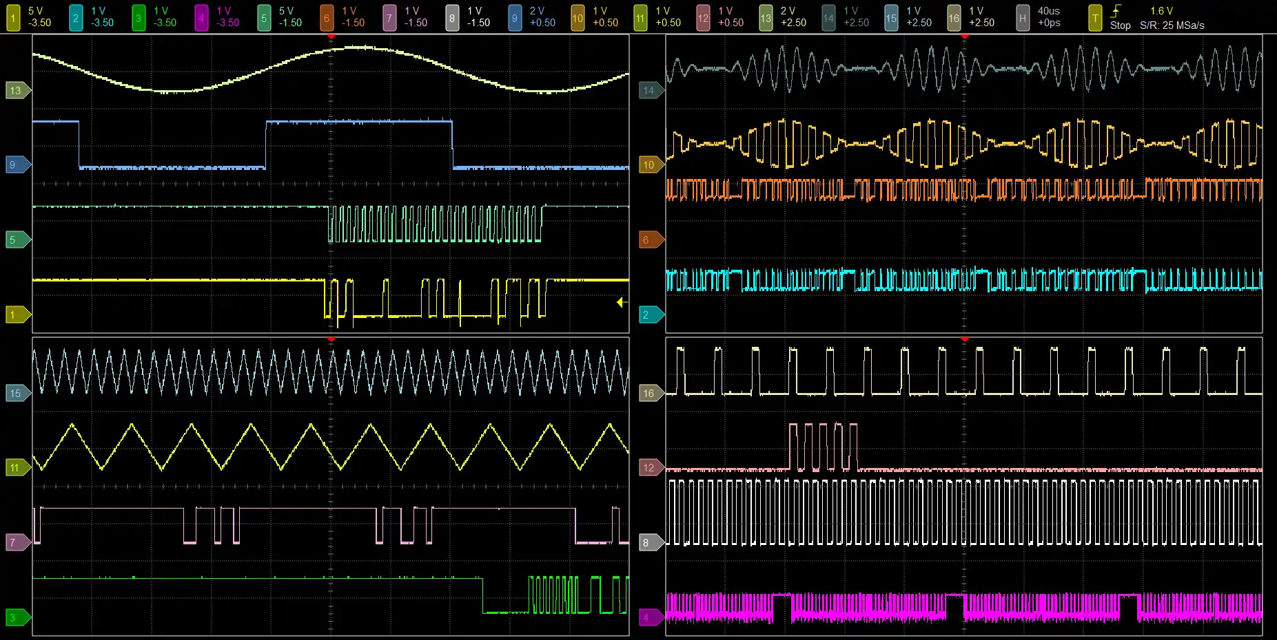
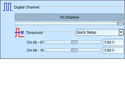
Multiple Devices Stack Mode
Support DSO stack mode, up to 4 devices (16 channels) can be stacked together in the same time.

Protocol Decode & Trigger Function
Provides, CAN/CAN-FD, I²C, LIN, MIPI I3C 1.1, ProfiBus, SPI, UART(RS232), USB1.1,… protocol decode and trigger function, which is able to trigger and decode on the specified Command/Address/Data...

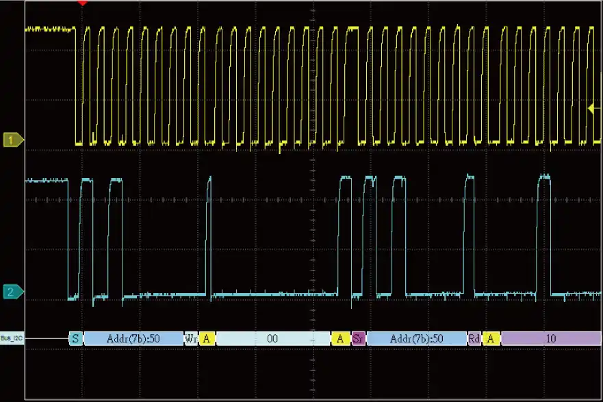
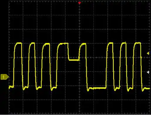
Decode the I2C waveforms

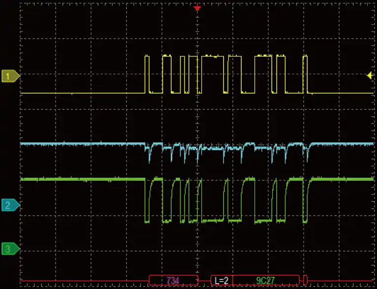
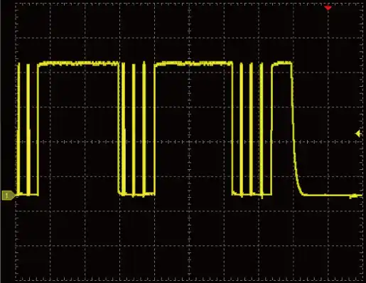
Decode the differential CAN signals with a differential probe. (CH1: Differential Probe, CH2: CAN H, CH3: CAN L)
※ Supports CAN-FD, CAN2.0

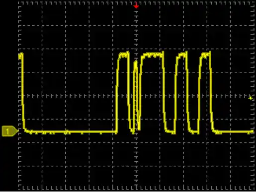
Runt Trigger - Positive Runt
Use 2 voltage thresholds and pulse width to trigger on either/ ±runt signals.

Runt Trigger - Negative Runt


Timeout Trigger
Trigger when no pulse is detected within a specified time, range from 2ns to 50s.

Width Trigger
Pulse width range from 8ns to 50s.
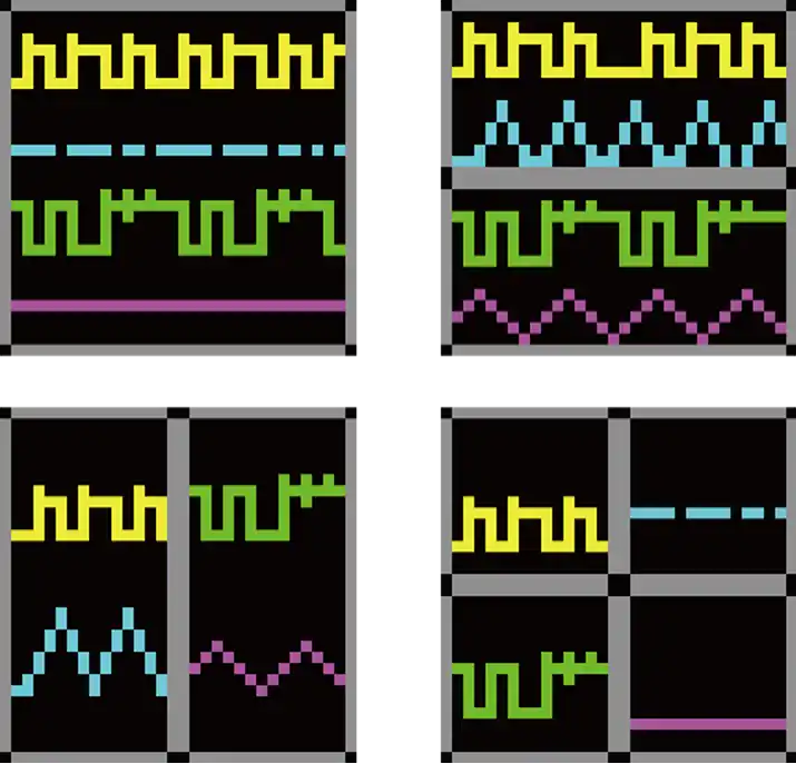
Multiple Windows

Multiple Window feature provides 4 display types (1x1, 2x1, 1x2, 2x2), which could displays 16 channels in maximum 4 different windows, provides clear waveform readability without lower the vertical resolution.

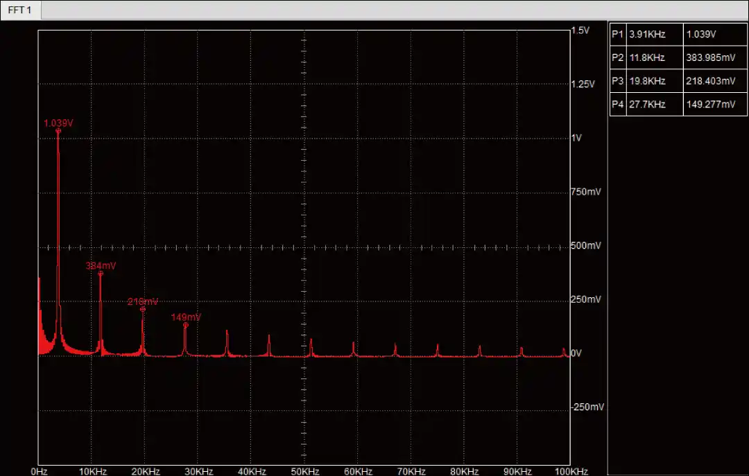
Spectrum analysis (Fast Fourier transform, FFT)

Apply FFT to the selected channel.

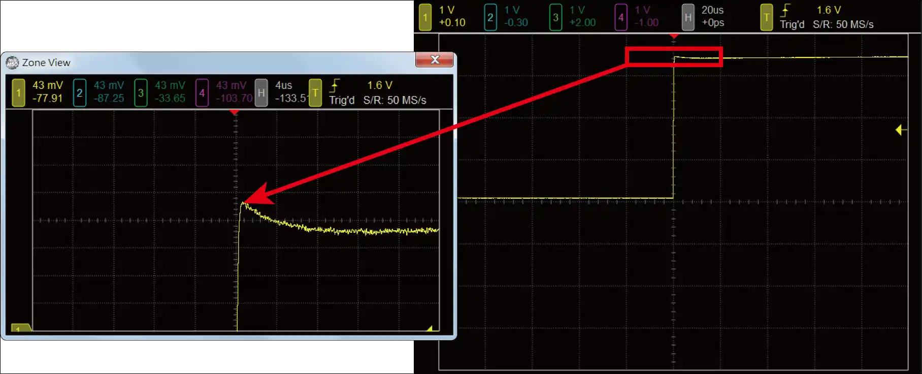
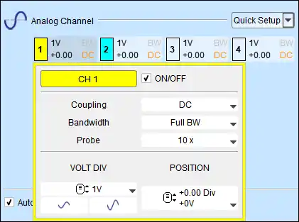
Vertical Offset & Zone View

Voltage division from 2mV/Div - 10V/Div combined with the channel independent Vertical Offset settings, which can be used for glitch measurement and analysis on DC power, and observing the ripple and overshooting voltage on DC offseted voltage. It is also possible to use 16Bit high vertical resolution mode (TS3124H/V) with the Zone View feature to observe the DC voltage and ripple signal together in the same time.

Digital Voltmeter, DVM

Provides voltage root-mean-square, voltage average and frequency counter function for the selected channel.

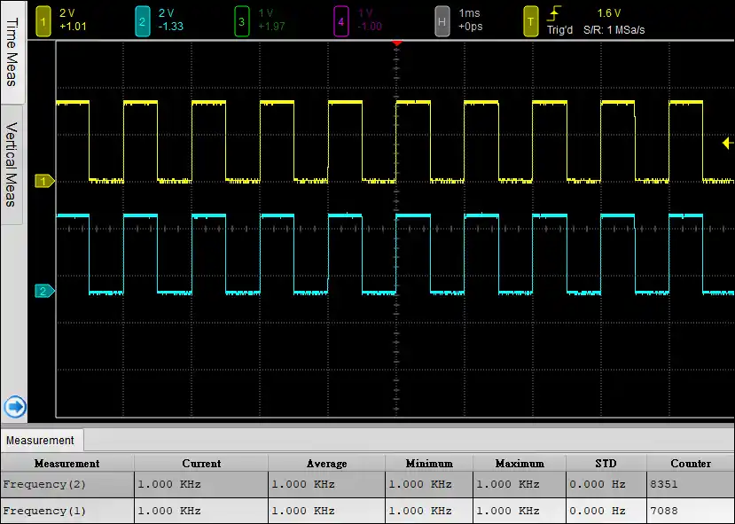
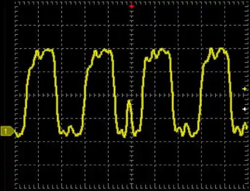
Measure 1 KHz, 2.5 Vpp square waveforms by the measurement function.

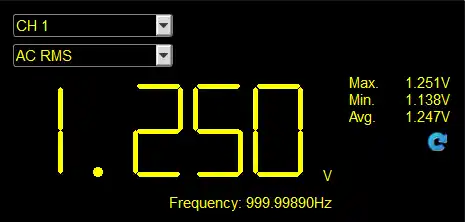
Measure 1 KHz, 2.5 Vpp square waveforms by the DVM function.
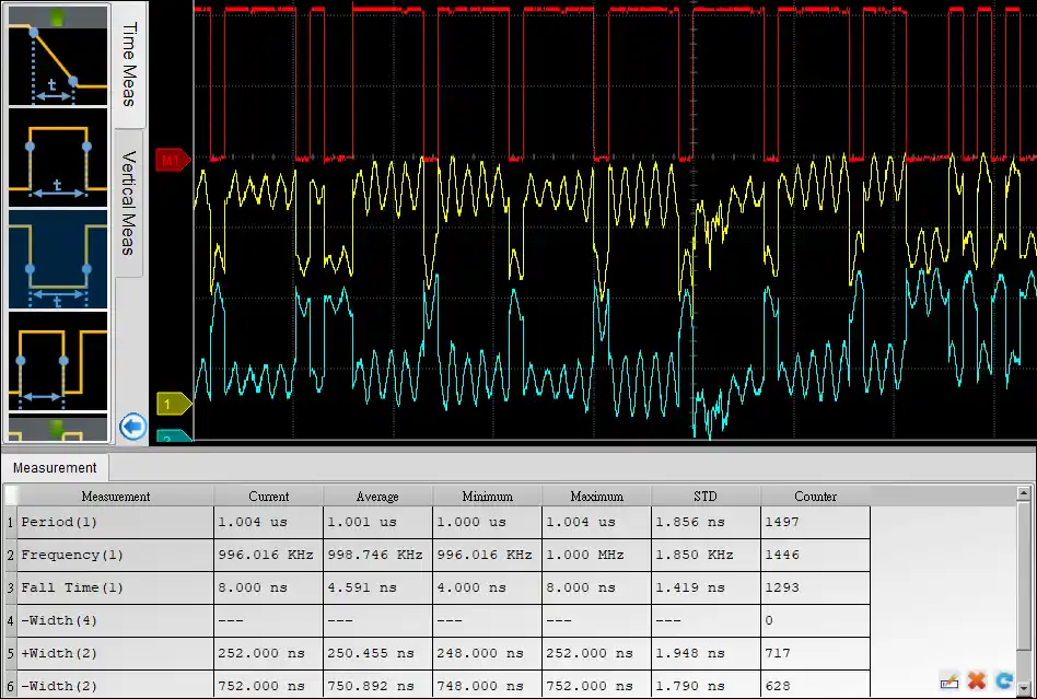
Measurement

More than 20 types of waveform measurements with customized threshold settings features, provides real-time update for vertical, time and channel to channel timing measurements with statistic features.
Time:
Frequency, Period, ±Duty, ±Period, Rise/Fall Time, Delay, Phase
Vertical:
VMax, VMin, VHigh, VLow, Vpp, VAmp, VMid, VMean, VRMS, ±Overshoot, Rise/Fall Preshoot
Counter:
Edge Count, ±Pulse Count
Math:
Add, Subtract, Multiple, Divide, XY, Absolute, Square Root, LogA, LnA, Exponential, Integral

Logic Analyzer (LA) Mode

• Capture digital waveforms and support bus decodes. Able to stack with a DSO to form as an MSO.

• Provides multiple storage modes, users could select to have long time recording or precision acquisition.


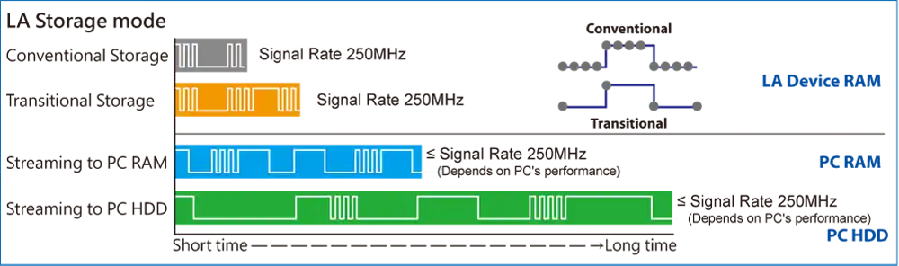
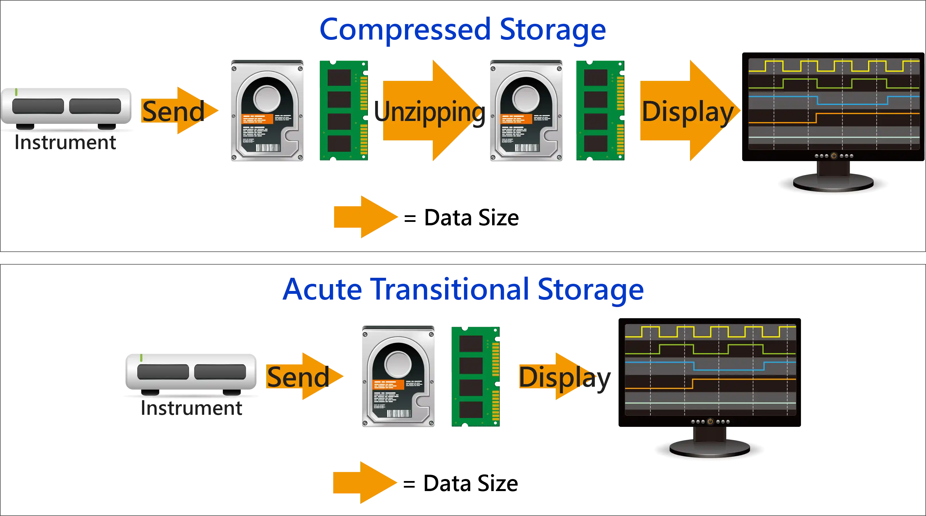
• Long Time Record: Transitional Storage VS Compressed Storage

For signal capture and analysis, usually require to record the signal for a long time. If the data is stored in a compressed way, it will cause your software to lag or even stop functioning when decompressing the data after it is sent back to the computer. Because PC memory size might insufficient for decompressed data size. To satisfy the requirement of smooth software operation and long-term recording without missing any data, the storage method adopted by the Acute analyzer is transitional storage rather than compression. After returning to the PC software, it doesn"t need to do the decompression. The decoded results can be displayed while the analysis is finished.

    Analog waveform
    Input Sensitivity: 2mV/div to 10V/div; Max. Sampling Rate: 1GS/s @ 1Ch
    Can be used with High Voltage probe, Differential probe or Current probe.

    Digital waveform
    Operation Range: ±30V
    Max. Timing Analysis: 2GS/s @ 8Ch

    Flow chart bus triggers

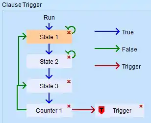
    Power trigger for serial bus, 8-states flow chart setting with Counter/Timer

    Detail parameters for each states

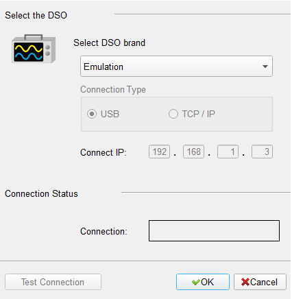
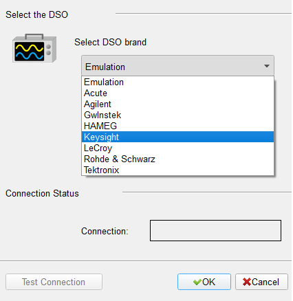
    Stack With Other Vendors of Oscilloscope

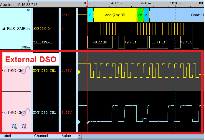
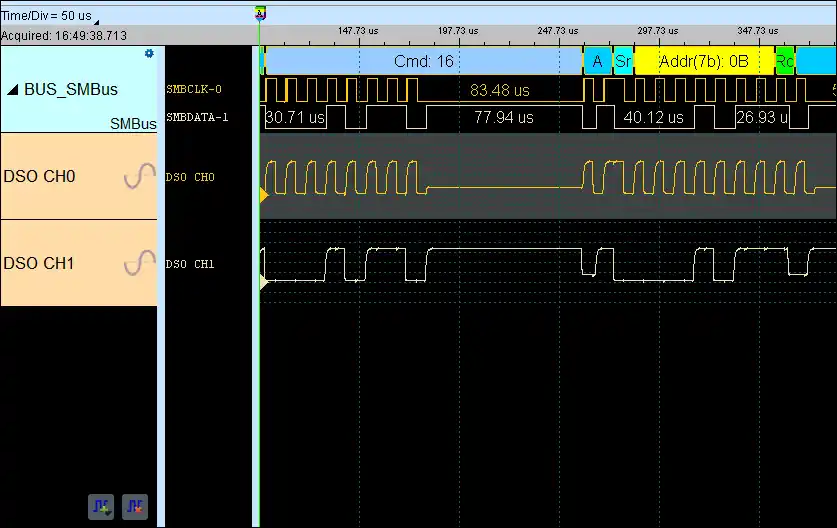
    MSO Enables Digital & Analog Channels
    (Using the same channels)

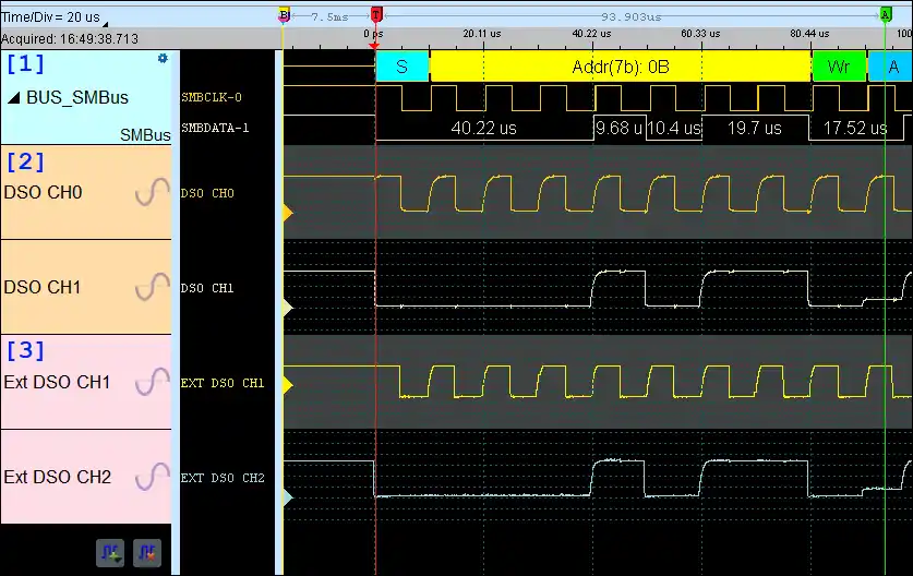
    Digital & Analog Signals From MSO and External DSO From Other Vendors
    *[1]: Decode & Digital Signals*[2]: MSO Analog Signals*[3]: External DSO Signals

    Protocol Analyzer (PA) Mode
    It is hardware decoding, may log protocol data very long time if without waveforms. Application timing: Preliminary protocol debug.

    Protocol Analyzer
    Show real-time protocol data.
    Application timing: massive protocol data with some idles in between.
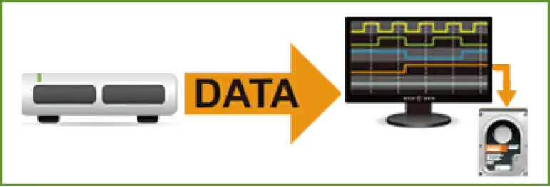
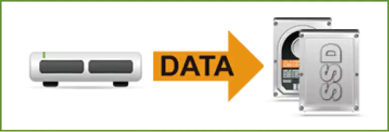
    Protocol Logger
    Like data logger, save massive data into SSD hard drive.
    Application timing: massive protocol data.

    Protocol Monitor
    Like dash cameras, record protocol data by the device’s memory only.
    Application timing: trigger event only happens in very long time.

    DSO Spec.
    Power source
    USB bus-power (+5V)
    Static power consumption
    4.5W
    Max power consumption
    7.7W
    Acquisition Mode
    Sample, Average, Envelope[*], Peak detect[*], High resolution
    8 bits Sampling [Record length]
    1 Ch @ 1 GS/s [512 Mpts];2 Ch @ 500 MS/s [256 Mpts];4 Ch @ 250 MS/s [128 Mpts]
    ≧12 bits Sampling [Record length]
    1 Ch @ 500 MS/s [512 Mpts];2 Ch @ 250 MS/s [256 Mpts];4 Ch @ 125 MS/s [64 Mpts]
    ≧14 bits Sampling [Record length]
    1 Ch @ 100 MS/s [256 Mpts];2 Ch @ 100 MS/s [128 Mpts];4 Ch @ 100 MS/s [64 Mpts]
    Input channels
    4
    Input coupling
    AC/DC
    Input impedance
    1 MΩ ∥ <19 pF
    Overvoltage protection
    ± 100 V (DC+AC peak)
    Ch-Ch isolation
    50dB @DC to 100MHz; 40dB @ 100MHz to 200MHz
    Ch-Ch skew
    100 ps between two channels with the same scale & coupling settings
    Bandwidth
    200 MHz
    Rise time
    1.75 ns @ 200 MHz; 3.5 ns @ 100 MHz; 7 ns @ 50 MHz
    Resolution
    8, 12, 14, 15, 16 bits
    Input sensitivity
    2 mV/div to 10 V/div
    Offset range
    ±150 V @ 2, 5, 10 V/div;
    ±15 V @ 0.2, 0.5, 1 V/div;
    ±1.5 V @ 2, 5, 10, 20, 50, 100 mV/div
    DC accuracy
    ±3% of Full-Scale
    Bandwidth limit
    20 MHz, 100 MHz or Full
    Protocol Trigger / Decode
    BiSS-C, CAN 2.0B/CAN FD, DALI, DP_Aux, HID over I2C, I2C, I2S, LIN2.2, MDIO, Mini/Micro LED, MIPI I3C 1.1, MIPI RFFE 3, MIPI SPMI 2, Modbus, PMBus, ProfiBus, SENT, SMBus, SPI, SVI2, UART, USB PD 3, USB1.1
    Electrical Validation (Protocol)
    I2C, I2S, MIPI I3C, MIPI RFFE, MIPI SPMI, PDM, SPI, UART(RS232)
    Cascade
    16 Ch
    LA Spec.
    Power Source
    N/A
    Static Power Consumption
    N/A
    Max Power Consumption
    N/A
    Hardware Interface
    N/A
    Timing Analysis (Asynchronous,Max. Sample Rate)
    2 GS/s
    State Clock Rate (Synchronous,External Clock)
    250MHz
    Storage
    Conventional Timing, Transitional Timing
    Channels
    16
    Total Memory
    N/A
    Timing Analysis
    Available Chs (Conventional / Transitional Timing) - Memory per Ch
    4GHz Timing [Available Chs] - Memory per Ch
    2GHz Timing [Available Chs] - Memory per Ch
    [8/7]-512 Mpts
    1GHz Timing [Available Chs] - Memory per Ch
    [16/14]-256 Mpts
    500MHz Timing [Available Chs] - Memory per Ch
    [16/16]-256 Mpts
    250MHz Timing [Available Chs] - Memory per Ch
    [16/16]-256 Mpts
    Channel to channel skew
    < 1ns
    Input channels
    16
    Input impedance
    75KΩ ∥ <2pF
    Max. (Non-destructive)
    ±50V
    Input operation
    ±30V
    Input sensitivity
    0.25Vpp @50MHz, 0.5Vpp @150MHz, 0.8Vpp @250MHz
    Threshold group
    2 (D0~D7, D8~D15 & CK0)
    Threshold range
    ±30V
    Threshold resolution
    50mV
    Threshold accuracy
    ±100mV + 5%*Vth
    Trigger resolution
    500ps
    Trigger types
    External, Manual, Multi Level, Setup/Hold Violation, Single Level, Timeout, Width
    Protocol Trigger
    BiSS-C, CAN2.0B/CAN FD, DALI, DP_Aux, eMMC 4.5, eSPI, HID over I2C, I2C, I2S, LIN2.2, LPC, MDIO, MII, Mini/Micro LED, MIPI I3C 1.1, MIPI RFFE 3, MIPI SPMI 2, Modbus, PMBus, Profibus, RGMII, RMII, SD 3.0 (SDIO 2.0), SENT, Serial Flash (SPI NAND), SMBus, SPI, SVI2, SVI3, SVID, UART, USB PD 3.1, USB1.1
    Protocol Analyzer
    BiSS-C, CAN2.0B/CAN FD, DALI, DP_Aux, eSPI, HID over I2C, I2C, I2S, LIN2.2, MDIO, MII, MIPI I3C 1.1, MIPI RFFE 3, Modbus, PMBus, Profibus, PWM, RGMII, RMII, SMBus, SPI, SVI3, SVID, UART, USB PD 3.1, USB1.1
    [Specifications] MSO3000 series
    [Manual] LA Mode
    [Manual] DSO Mode
    [Software] MSO3000 series
    [Driver] USB 3.0 driver
    [SDK] DSO
    [SDK] DSO AqVISA
    [SDK] LA AqLAVISA
    [SDK] Protocol Decode (C++)

    We use cookies to elevate your user experience and enhance the quality of our site. To find out more or adjust cookie settings, click here .