Use an oscilloscope for SPI electrical validation to ensure compliance with defined specifications. After an extended burn-in test, the oscilloscope confirms that the electrical characteristics of the signal meet the required standards.
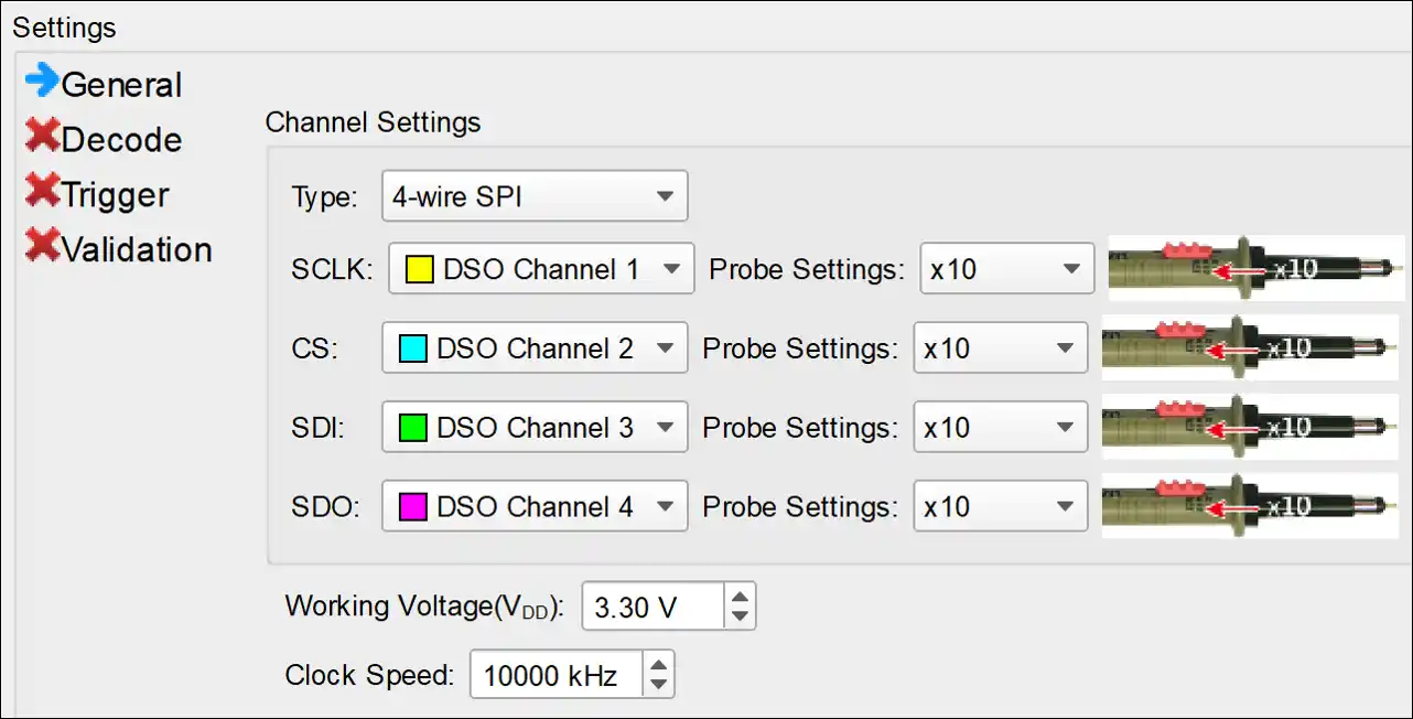
1. General Settings: Channel sources, working voltage and speed
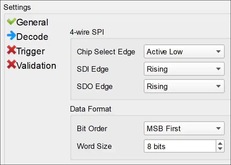
2. Decode Settings:In the Decode Settings, it requires you to setup the SPI data format and the Latching Edge of each channel. The SPI data format set here is applied both to the Decode and Trigger Settings.
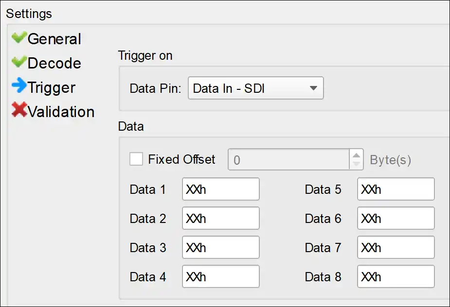
3. Trigger Settings: Setup the data address and which data pin to trigger.
4. Electrical Validation Parameter Settings: Frequency, Timing, Voltage limitation
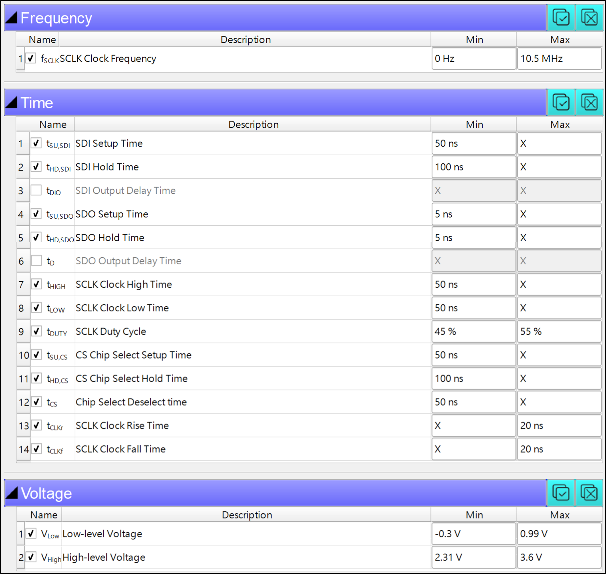
There are no standard measurement limits defined for SPI bus. Therefore, it is recommended to
define your own limits while validate SPI signals.
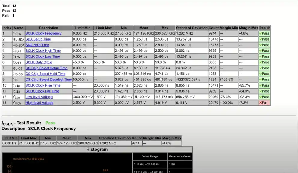
This section displays 3 characteristics table, including
• Frequency
• Timing parameters
• Voltage requirements
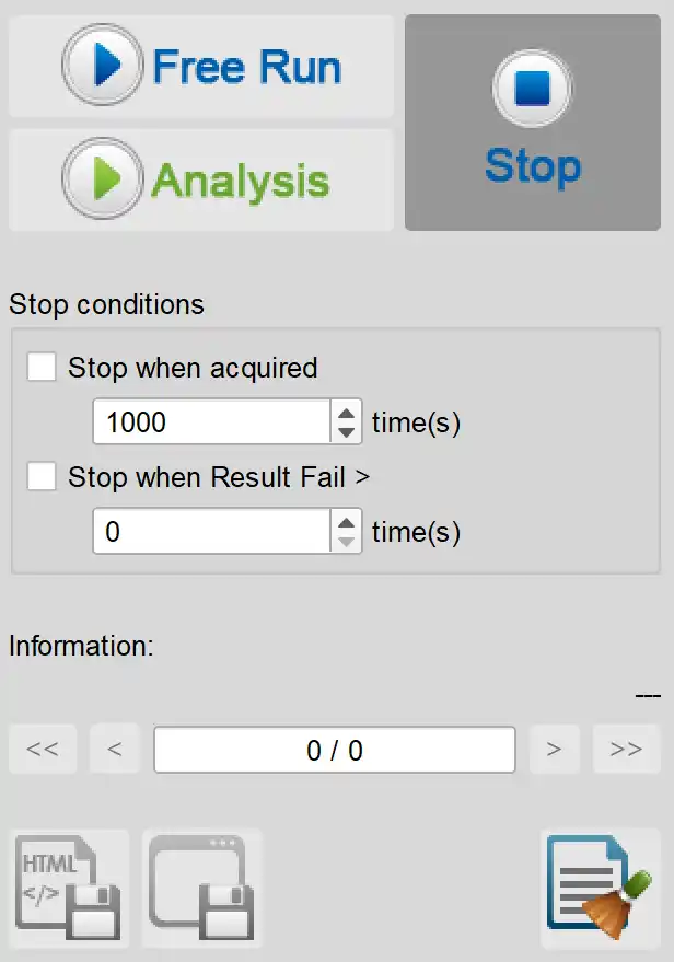
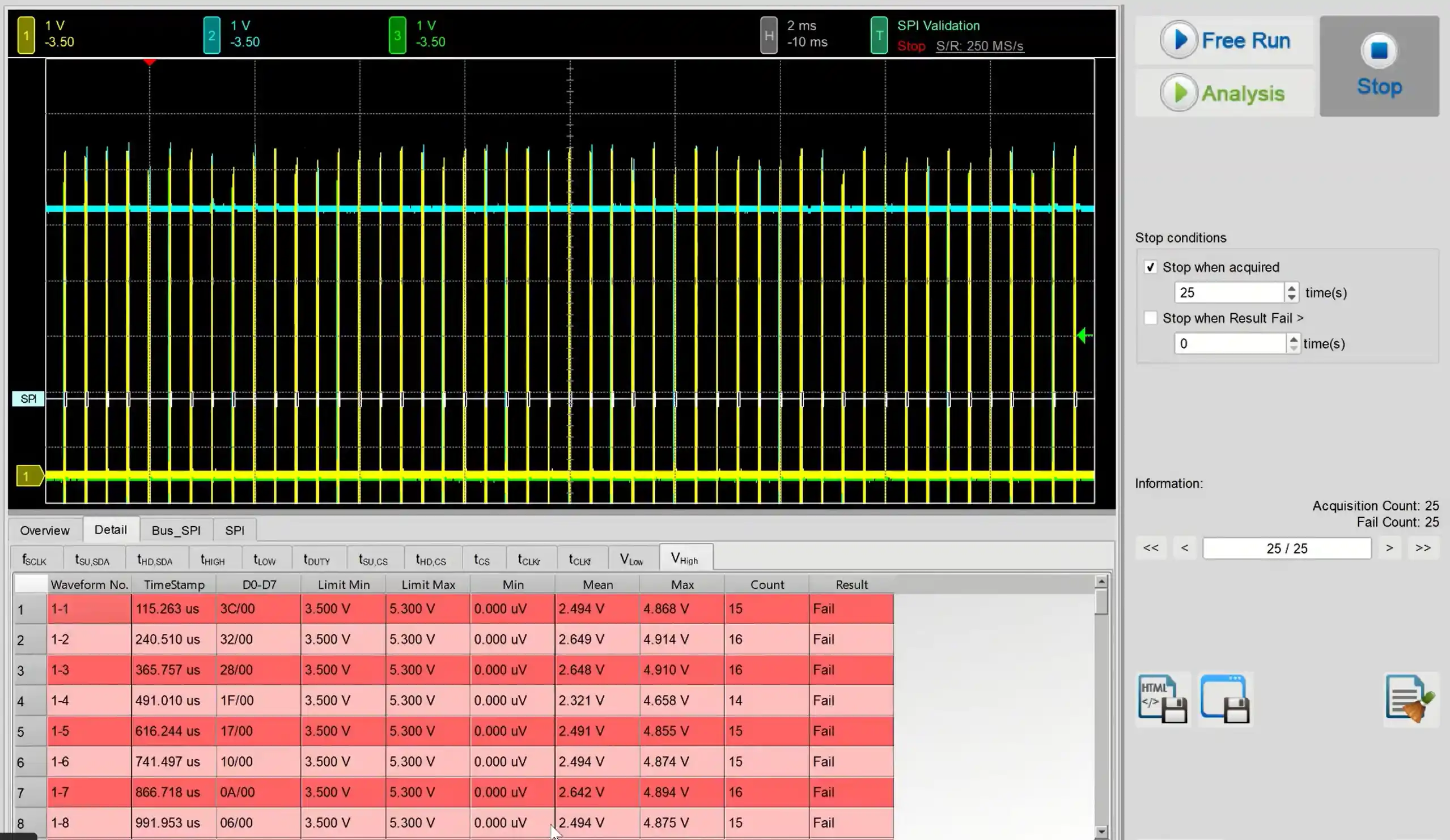
Frequency
Name
Description
Min
Max
fSCLK
SCLK Clock Frequency
0 Hz
10.5 MHz
Time
Name
Description
Min
Max
tSU,SDI
SDI Setup Time
50 ns
X
tHD,SDI
SDI Hold Time
100 ns
X
tDIO
SDI Output Delay Time
X
X
tSU,SDO
SDO Setup Time
5 ns
X
tHD,SDO
SDO Hold Time
5 ns
X
tD
SDO Output Delay Time
X
X
tHIGH
SCLK Clock High Time
50 ns
X
tLOW
SCLK Clock Low Time
50 ns
X
tDUTY
SCLK Duty Cycle
45 %
55 %
tSU,CS
CS Chip Select Setup Time
50 ns
X
tHD,CS
CS Chip Select Hold Time
100 ns
X
tCS
Chip Select Deselect time
50 ns
X
tCLKr
SCLK Clock Rise Time
X
20 ns
tCLKf
SCLK Clock Fall Time
X
20 ns
Voltage
Name
Description
Min
Max
VLow
Low-level Voltage
-0.3 V
0.99 V
VHigh
High-level Voltage
2.31 V
3.6 V
5. Software EV control panel:
Stop Conditions: Stop when acquired X times Stop when Result Fail > X times
Information: Select waveform
Save File: Save as Html Save as .MOW (Software format)
YouTube Video
Electrical Validation Solution PDF
We use cookies to elevate your user experience and enhance the quality of our site. To find out more or adjust cookie settings, click here .