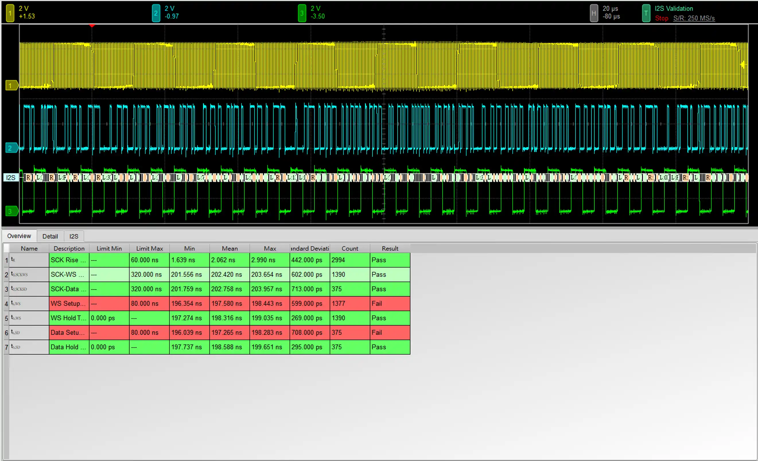
I²S Electrical Validation
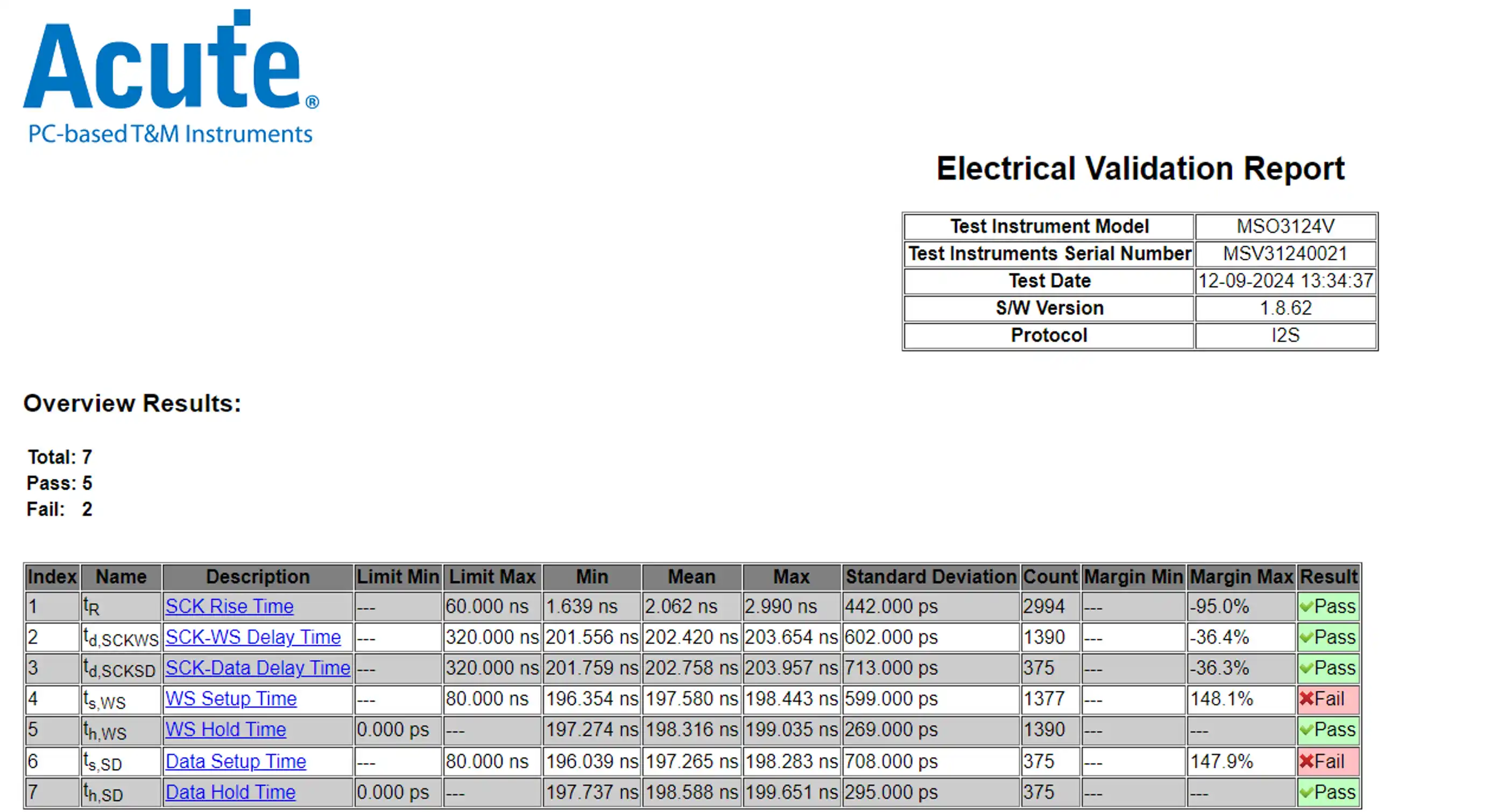
Overview Report
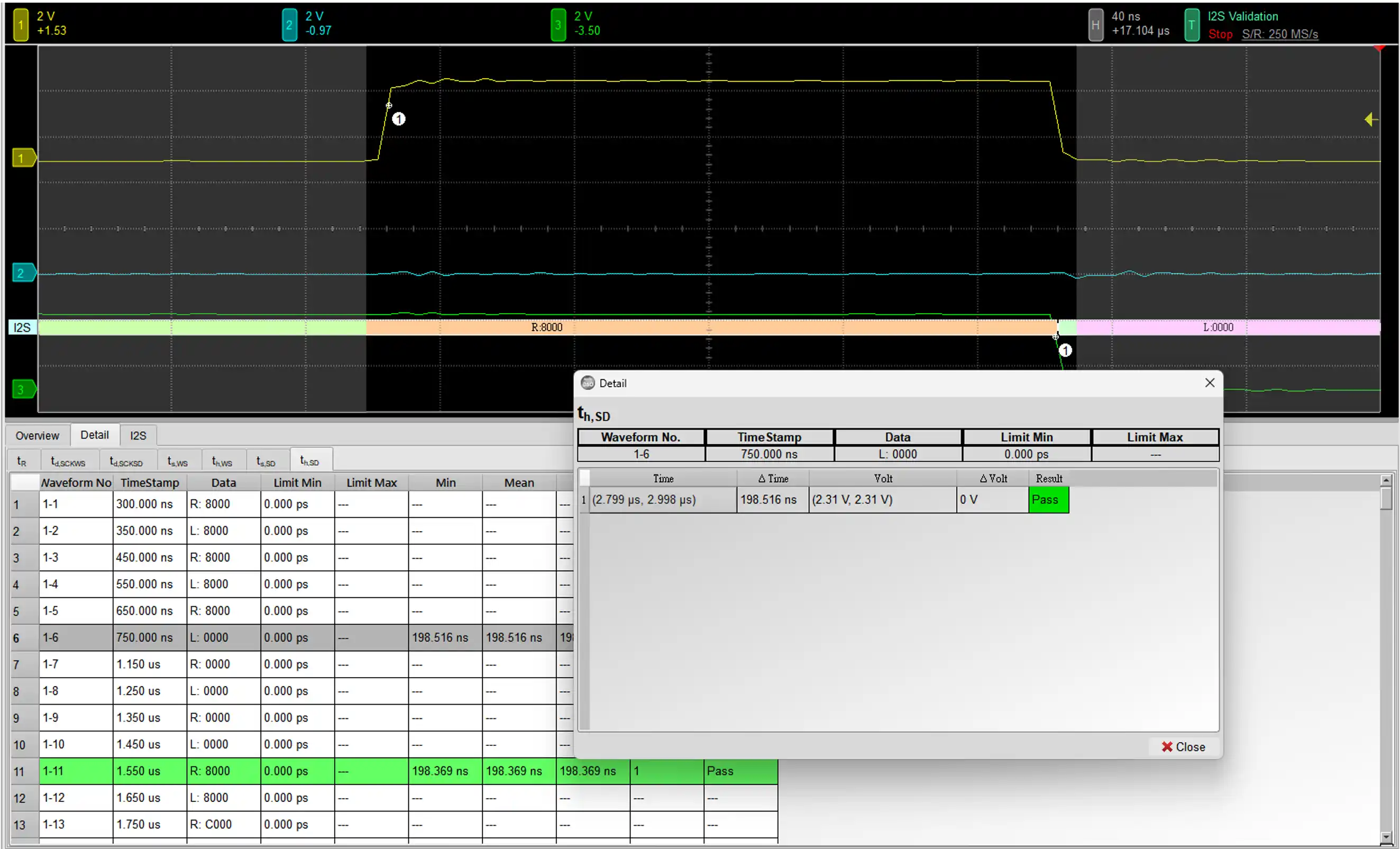
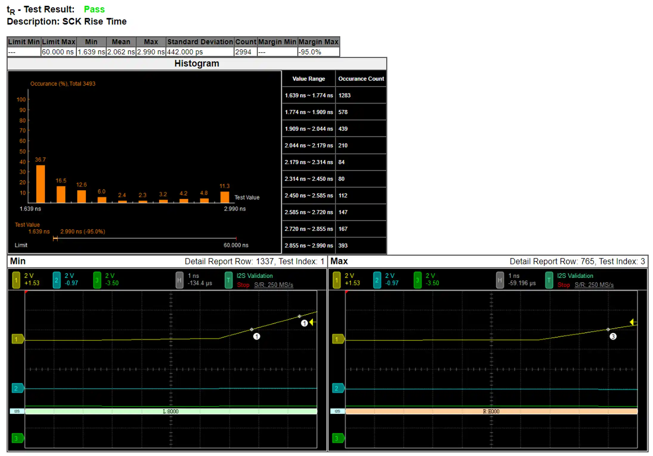
Reference Point Dialog & Waveform:
HTML Report
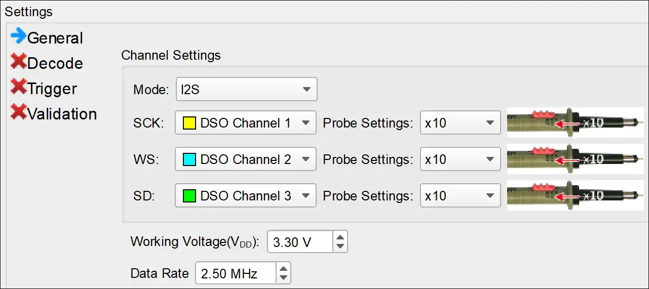
1. General Settings: Setup the bus configuration, including I2S mode type (I2S, Left Justified, PCM, TDM), the channel settings, working voltage and the data rate of I2S.
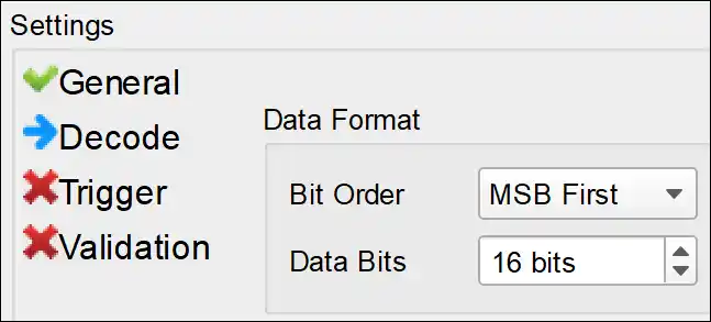
2. Decode Settings: Setup the I2S data format. Bit order is either MSB First or LSB First. Data Bits can be set in a range of 1-32 bit(s).
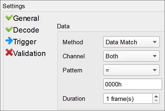
3. Trigger Settings
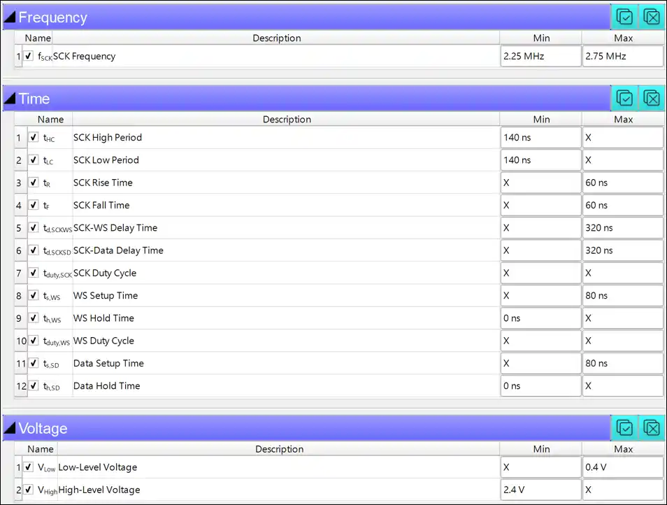
This section displays 3 characteristics table, including
1. Frequency
2. Timing Parameters
3. Voltage requirements
The default values are referenced from the I2S specification rev3.0.
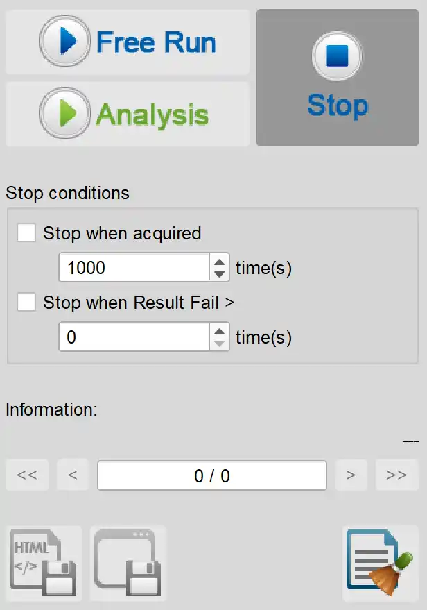
Stop Conditions:
Stop when acquired X times
Stop when Result Fail > X times
Information:
Select waveform
Save File:
Save as Html
Save as .MOW (Software format)
Electrical Validation Solution PDF