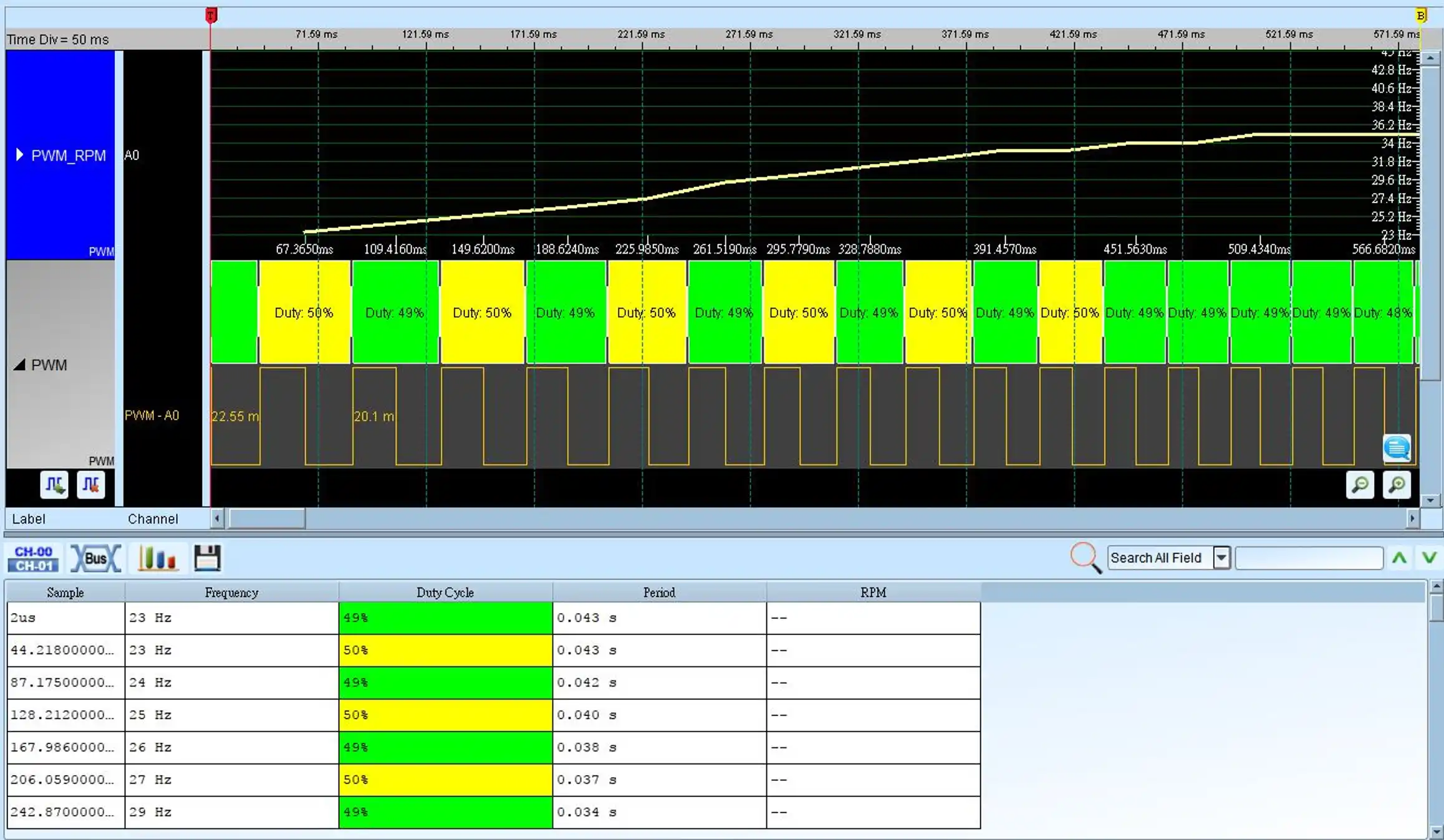
Popular Keywords

PWM

PWM (Pulse Width Modulation) is not a bus analysis protocol but rather a highly effective technique for controlling analog circuits using the period of pulse width. It finds extensive applications in power control, speed control, brightness control, and temperature control.

In power control, PWM is commonly used to regulate voltage or power applications. By varying the width of the pulses, the average power output can be adjusted, allowing effective control of the power supply. This is commonly seen in various devices, including power supplies and motor controllers.

In temperature control, PWM also plays a crucial role. By adjusting the energization time of heating elements, fine temperature control can be achieved. This is practical in many systems, such as fan control in electronic devices and cooling systems with heat dissipation fans.

Additionally, PWM is frequently applied in brightness control. In lighting systems or display screens, adjusting the brightness of lamps or backlighting through PWM enables precise control of light intensity. This not only provides users with a better visual experience but also contributes to energy conservation.

In terms of signals, PWM is commonly used in RPM (speed), temperature, and brightness control. By adjusting the width of pulses, the operational states of relevant devices can be precisely controlled, meeting the requirements of various applications.

Logic Analyzer

TB3016F

TB3016F

TB3000 series Specifications PDF

MSO2116E (w/ analog channels)

MSO2116E

MSO2000 series Specifications PDF

Model TB3016F MSO2116E
Decode y y
Analog Channels y

PWM Decode

Select Time(X)-Duty(Y)

Select Time(X)-Freq.(Y)

Select Time(X)-RPM(Y)
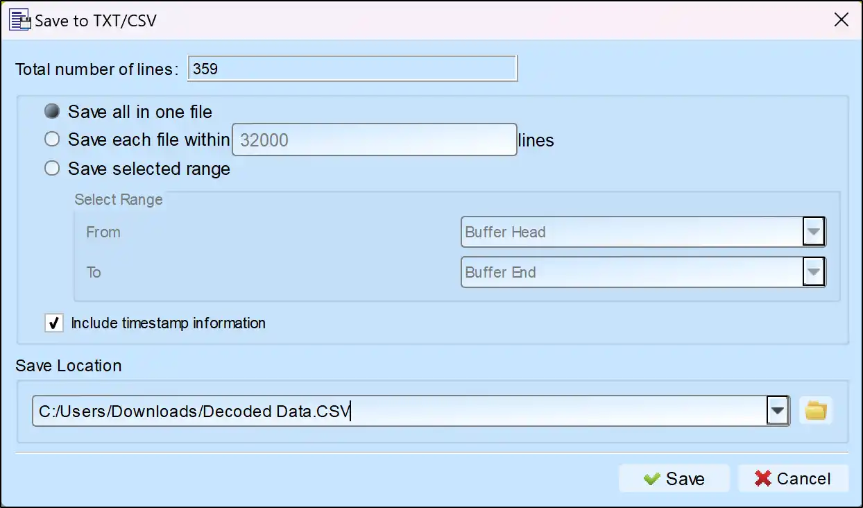
Save as TXT/CSV

In Logic Analyzer mode, click the icon above the report area to save the decoded data as a TXT/CSV file.

Export Icon

PWM Decoding Setup Steps

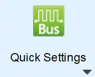
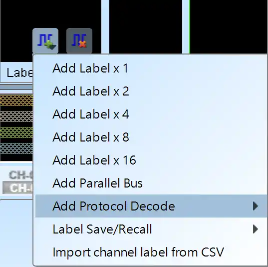
1. Click Quick Settings or Add Protocol Decode to select a protocol for logic analyzer capture.

2. Select PWM for decoding.

3. If you use Quick Settings, the system will recommend configurations for trigger type, sampling rate, voltage threshold, and channel settings.

4. Click the icon to access the Decode Settings screen.
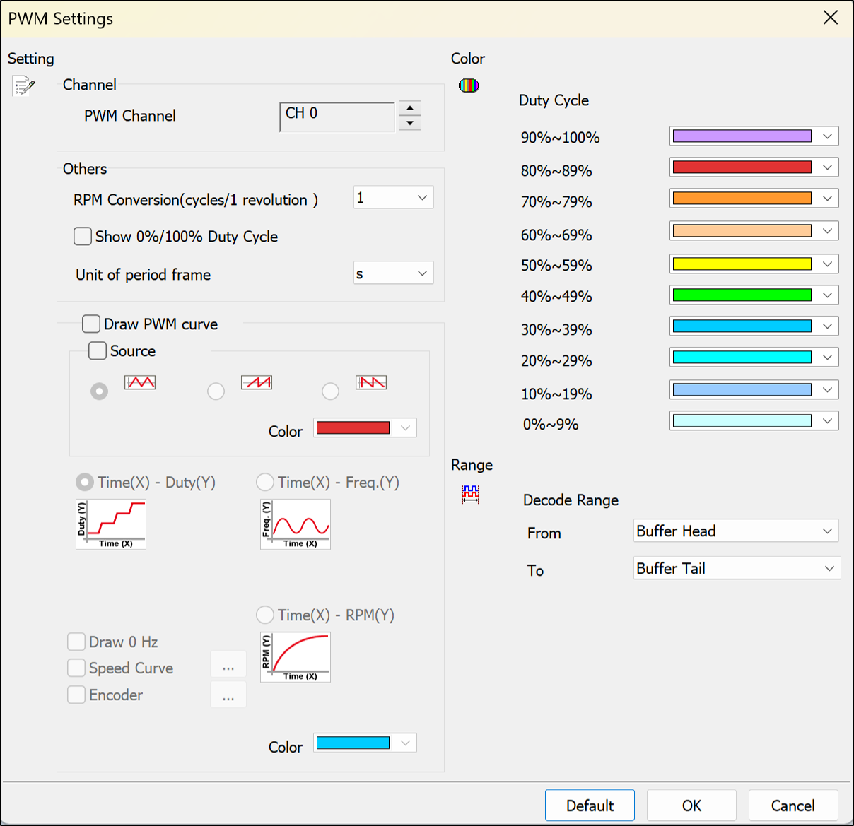
Image 1
Image 2

Decode Settings

Channel: Show the selected channel.

Draw PWM curve:

Source: Show the source waveform of the PWM.

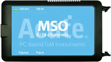
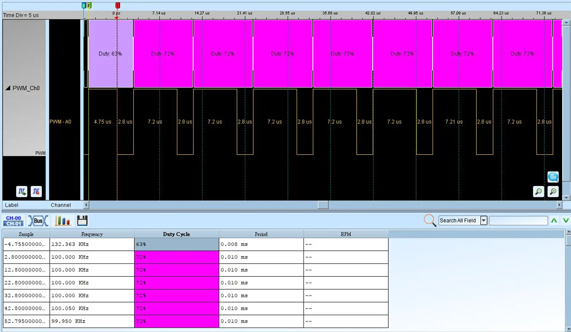
Time(X)-Duty(Y): Show the curve diagram with Time(X) and Duty(Y)

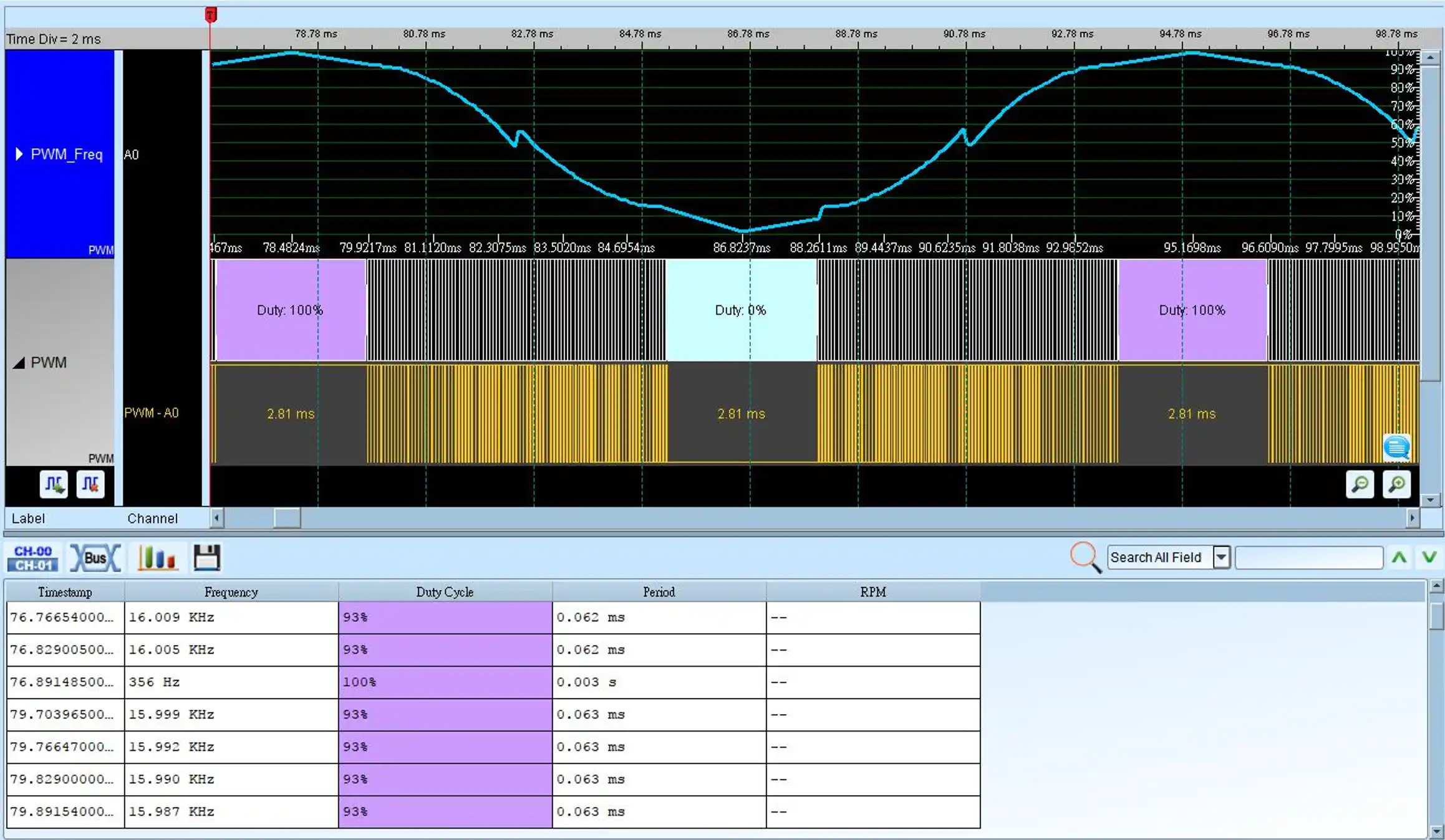
Time(X)-Freq.(Y): Show the curve diagram with Time(X) and Freq.(Y)

Time(X)-RPM(Y): Show the curve diagram with Time(X) and RPM(Y)

Draw 0% and 100%: When select the Time(X)-Duty(Y) drawing and check Draw 0% and 100%, the program will draw this duty curve of 0% or 100%; it will draw this duty curve of 0% or 100% when uncheck Draw 0% and 100%.

Draw 0 Hz: When select the Time(X)-Freq.(Y) drawing and check the item Draw 0 Hz, will show the Frequency from 0 Hz at Y axis.

PWM Decoding Examples

We use cookies to elevate your user experience and enhance the quality of our site. To find out more or adjust cookie settings, click here .