BiSS-C
BiSS-C (bidirectional serial synchronous C-mode) is an open-source, full-duplex, serial synchronous protocol introduced by iC-Haus GmbH. It is specifically designed to meet the real-time, bidirectional, high-speed communication requirements of sensors, and is hardware-compatible with the industrial-standard serial synchronous interface (SSI).
It is primarily applied in areas such as motor control and position sensors. In motor control applications, BiSS-C enables efficient data transmission, supports real-time position and velocity feedback, contributing to improved precision control and motion performance of motors. Additionally, it is widely used in position sensors for various applications that require accurate position measurement, such as machine tools, robots, and automation systems. The synchronous communication of BiSS-C ensures the accuracy and real-time nature of position data, making it a reliable choice for position sensors.
In terms of signals, BiSS-C uses two main signal lines: master clock (MA) and slave data out (SLO). MA is the signal from the master control, used for sending commands and control messages, while SLO is the synchronous data link responsible for actual data transmission.
The application of BiSS-C is not limited to just motor control and position sensors; it extends to other automation and control systems that require efficient and reliable communication.
Logic Analyzer
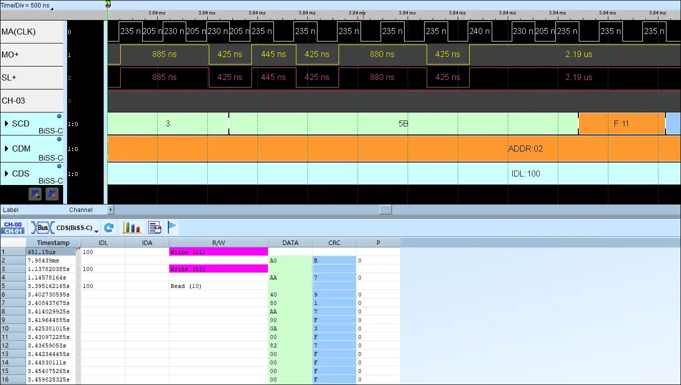
BiSS-C Decode
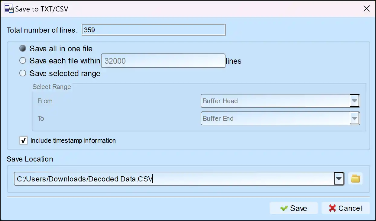
Save as TXT/CSV
In Logic Analyzer mode, click the icon above the report area to save the decoded data as a TXT/CSV file.

BiSS-C Decoding Setup Steps
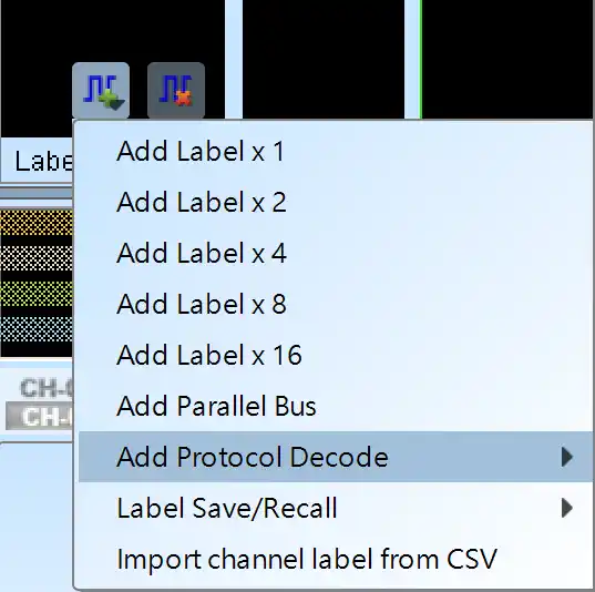
1. Click Quick Settings or Add Protocol Decode to select a protocol for logic analyzer capture.
2. Select BiSS-C for decoding.
3. If you use Quick Settings, the system will recommend configurations for trigger type, sampling rate, voltage threshold, and channel settings.
4. Click the icon to access the Decode Settings screen.

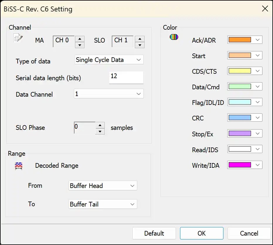
Decode Settings
MA / SLO: Setting the channel of MA and SLO.
Type of data: Setting the type you want to decode. It include “Register Data-CDM”, “Register Data-CDS”, “Single Cycle Data”.
Serial data length(bits): Setting the data length when Single Cycle Data mode.
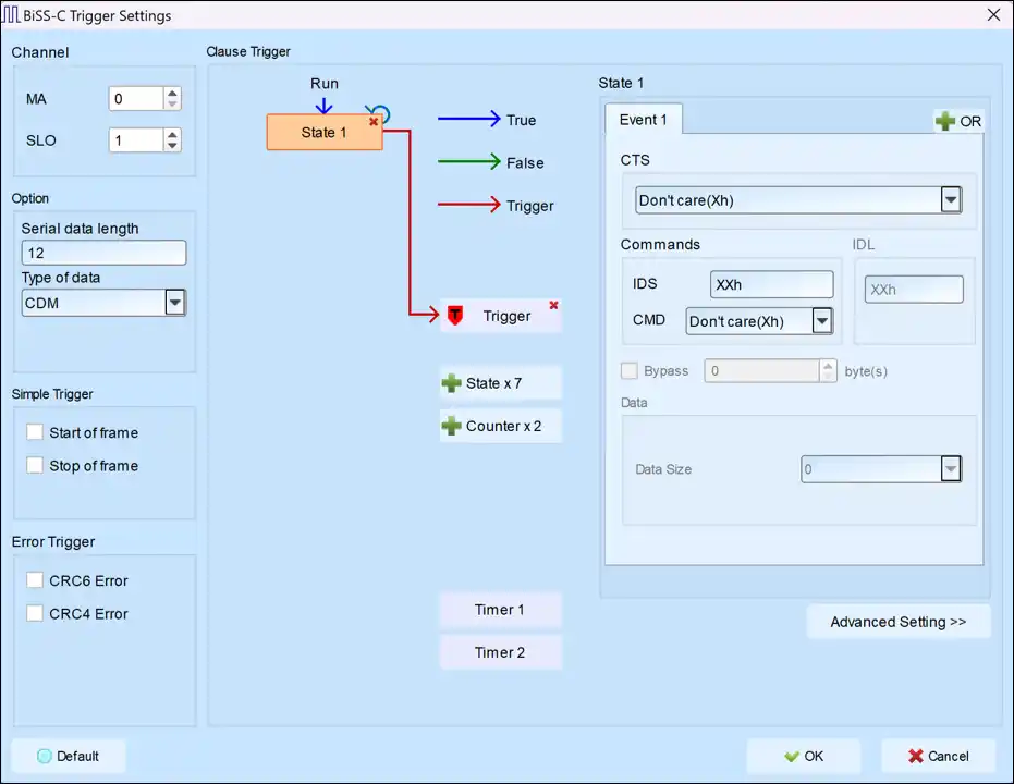
Trigger Settings
Channel: Select the desired channels.
Option:
Serial Data Length: Set the SCD packet length. The default is 12 bits, and the maximum is 255 bits.
Type of Data: Choose between CDM or CDS packets.
Simple Trigger: Use the specific trigger function for BiSS-C.
Error Trigger:
CRC6 Error/CRC4 Error: Trigger on CRC6 or CRC4 errors in BiSS-C.
Clause Trigger: Refer to the Clause Trigger chapter for more information.
State: View detailed trigger conditions for each state on the left. Enter or select trigger values for the CTS, Commands, IDL, and Data fields. The default value, "XX," indicates "don’t care."
