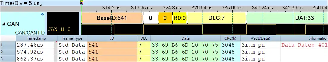
The Controller Area Network (CAN) protocol, featuring versions 2.0A (Basic CAN, 11 bits) and 2.0B (Extended CAN or Peli CAN, 29 bits), encompasses four message types: Data Frame, Remote Frame, Error Frame, and Overload Frame. The CAN Bus utilizes two primary data outputs known as CAN High (CAN_H) and CAN Low (CAN_L). In the context of automobile electronics applications, the signal voltage specifications are critical. CAN_H operates within the voltage range of 2.5V to 3.5V, while CAN_L maintains a voltage range of 1.5V to 2.5V.
Furthermore, the CAN protocol exhibits flexibility in data transmission through the incorporation of CAN FD (CAN with Flexible Data-Rate). In CAN FD mode, data transfer involves 64 bytes per data, inclusive of CRC17/CRC21 for enhanced reliability and integrity. This adaptability in data rate is instrumental in meeting the diverse requirements of modern automobile electronics.
Differential signal analysis holds significant importance in the fields of vehicle, robot design, and automation industries. The demand for protocols in the context of electric vehicles is notably on the rise. For the effective operation of Advanced Driver Assistance Systems (ADAS) and Automatic Driving Systems (ADS), the measurement of protocols becomes imperative, especially for large-scale systems and extensive sensors, which may include LiDAR/Radar. Commonly employed protocols in this domain encompass RS485 (EIA485), SENT, CAN, LIN, Flexray, Ethernet AVB (MII), and others.
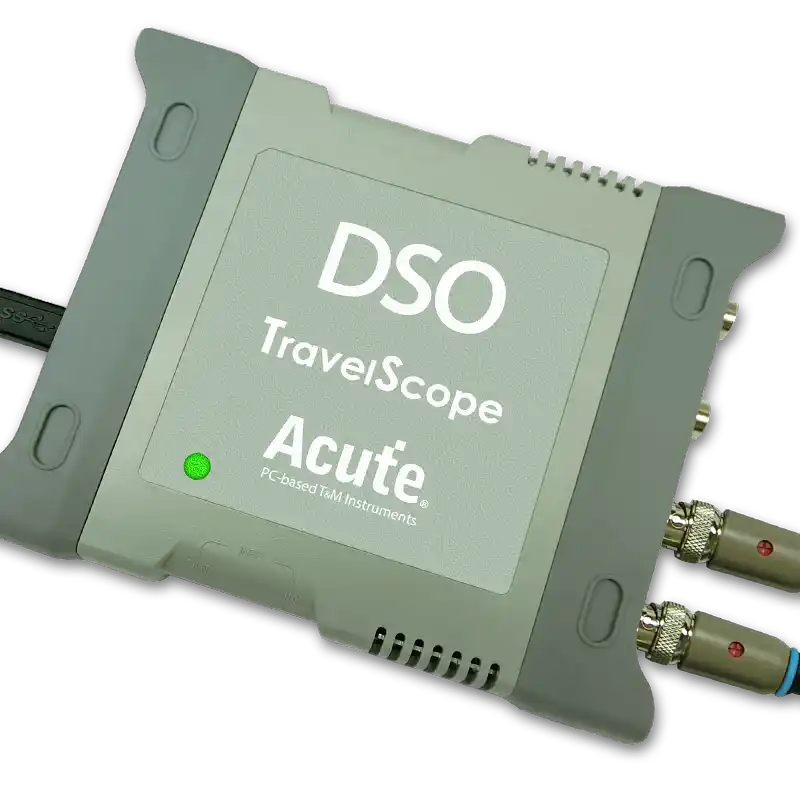
Acute Technology provides logic analyzers and oscilloscopes with CAN decoding capabilities.
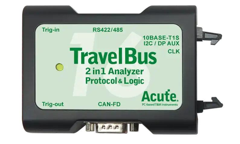
The TB3016B logic analyzer is able to directly measure and decode differential signals, including CAN 2.0B, CAN FD, DP AUX, RS485, RS422, and 10BASE-T1S.
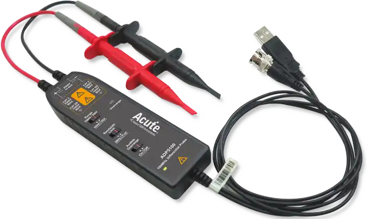
When using an oscilloscope to measure CAN or CAN FD signals, it is essential to determine whether the signal is differential or single-ended. For differential signals, use a differential probe such as the ADP1025 to prevent measurement errors or abnormalities caused by the lack of grounding.