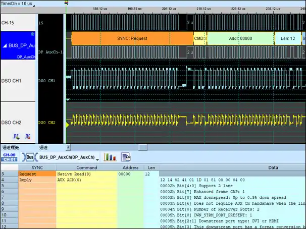
DP AUX (DisplayPort Auxiliary channel)
DP AUX Decode / Waveforms (Digital + Analog):
Multiple Protocols (I2C + DP AUX) Decode / Waveforms
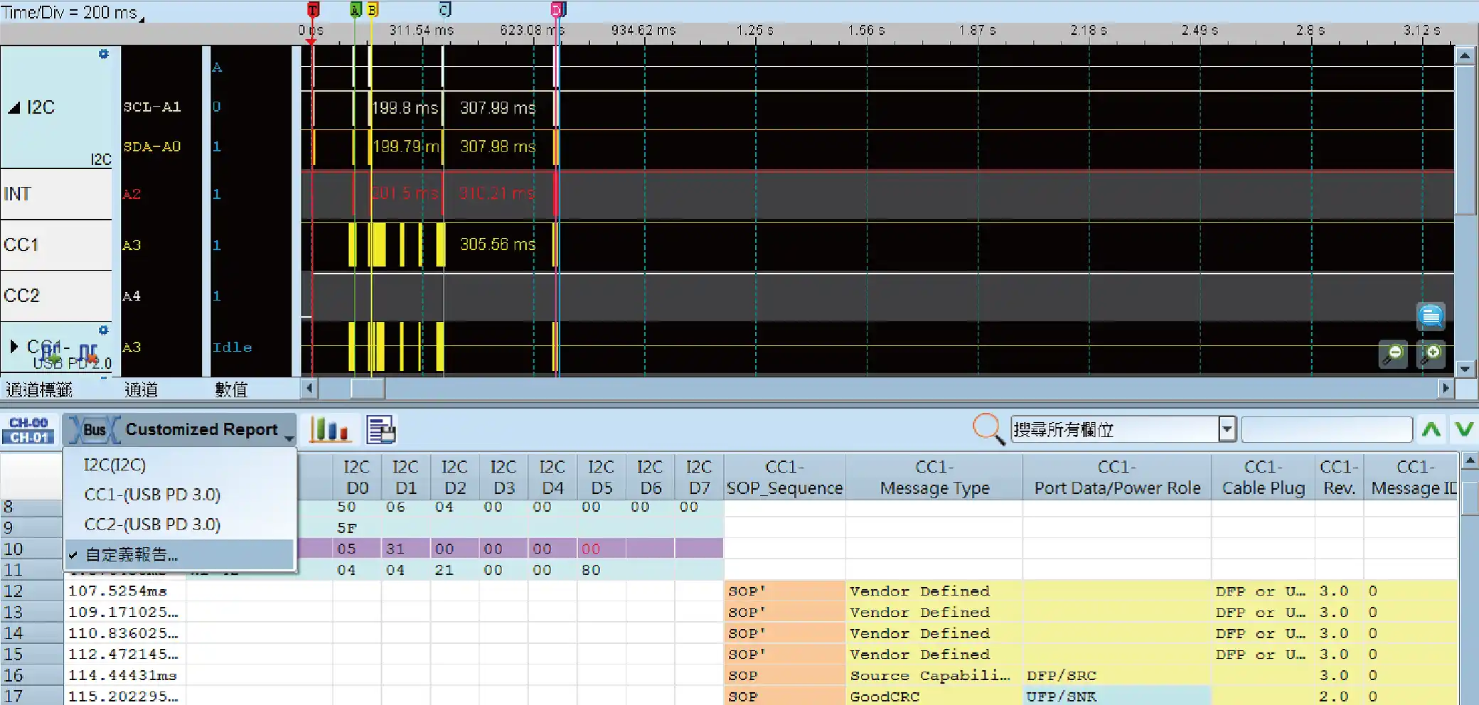
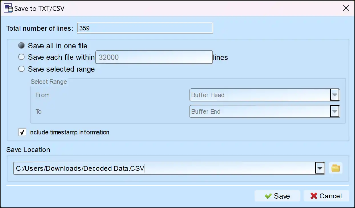
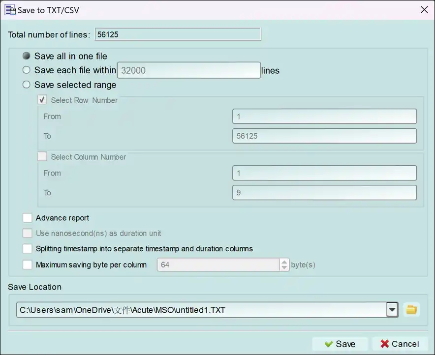
Save as TXT/CSV
In Logic Analyzer mode, click the icon above the report area to save the decoded data as a TXT/CSV file.

DP AUX Decoding Setup Steps
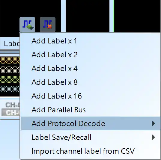
1. Click Quick Settings or Add Protocol Decode to select a protocol for logic analyzer capture.
2. Select DP_AuxCH for decoding.
3. If you use Quick Settings, the system will recommend configurations for trigger type, sampling rate, voltage threshold, and channel settings.
4. Click the icon to access the Decode Settings screen.

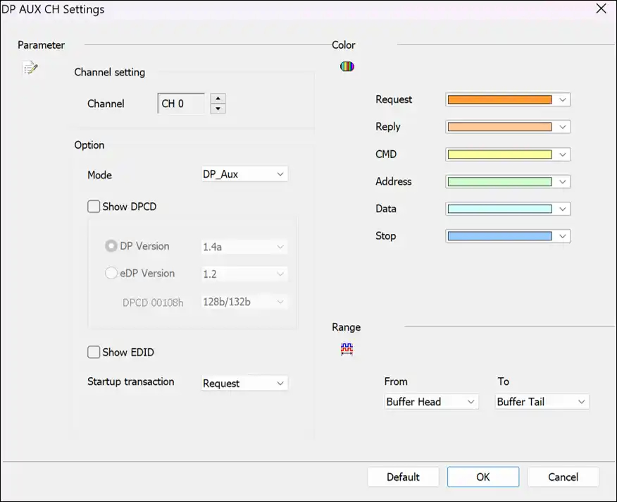
Decode Settings
Channel: Set the channel to decode
Show DPCD: Show the Display Port Configuration data.
Mode: Choose the mode DP_Aux/HPD/PWR
Startup transaction: Set the transaction type of the first frame
Reply Timeout: Set the value of timeout
Protocol Analyzer DP AUX Decode
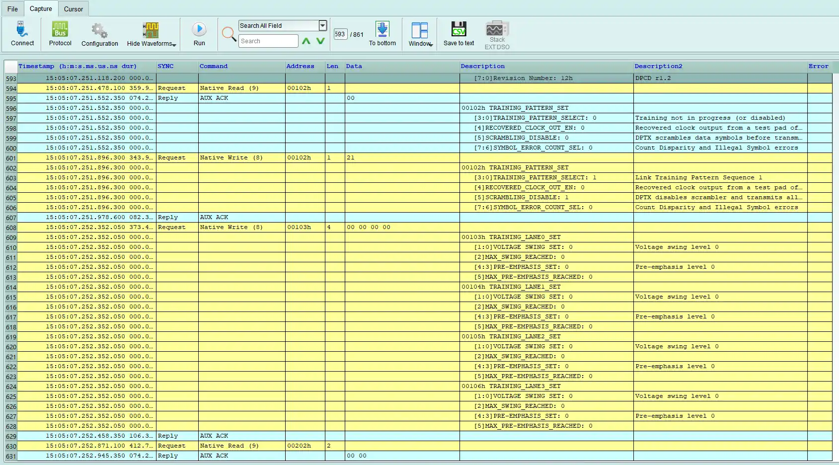
Save as TXT/CSV
In Protocol Analyzer mode, click the icon above the report area to save the decoded data as a TXT/CSV file.

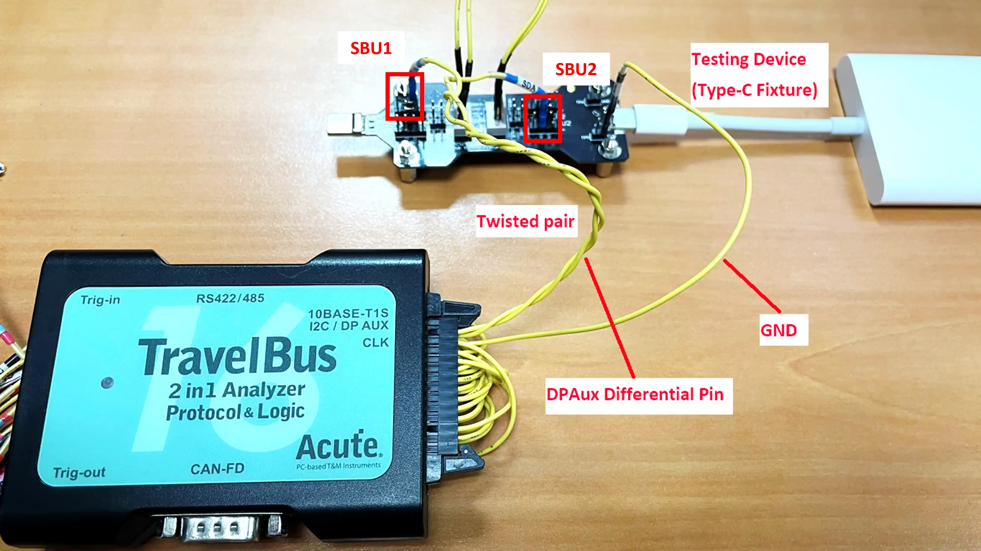
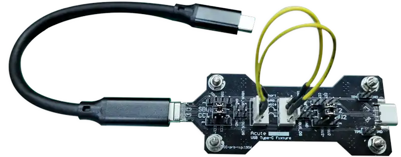
Use a USB Type-C adaptor to extract the DP AUX differential signals, then measure them directly with the TB3016B.
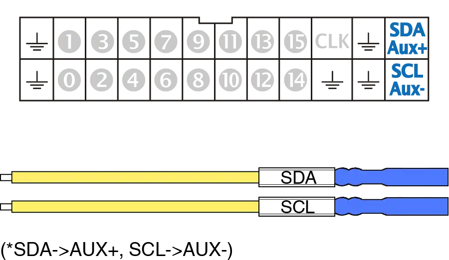
MSO2000 Series Logic Analyzer
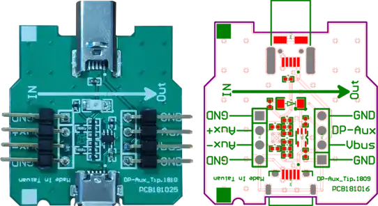
Use a USB Type-C adaptor to extract the DP AUX differential signals, convert them to single-ended signals using a DP AUX adaptor, and then measure them with the MSO2000 series logic analyzer.
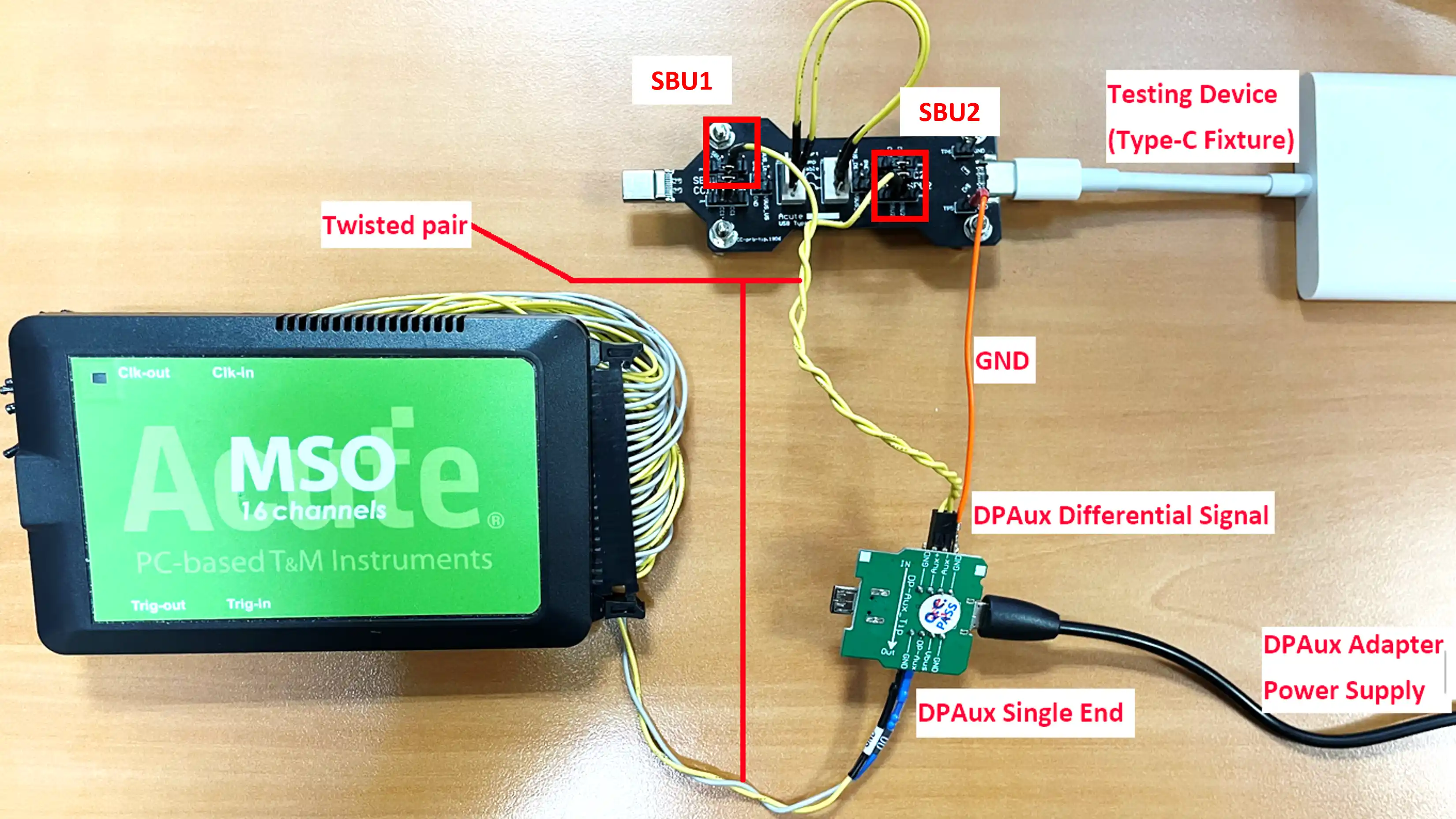
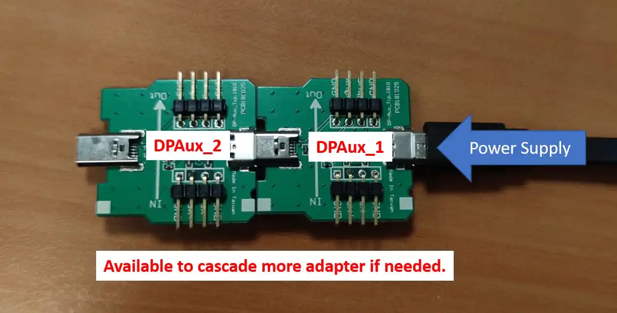
Cascade multiple DP AUX adapters:
DP AUX Decoding Examples