
SMBus
SMBus Decode
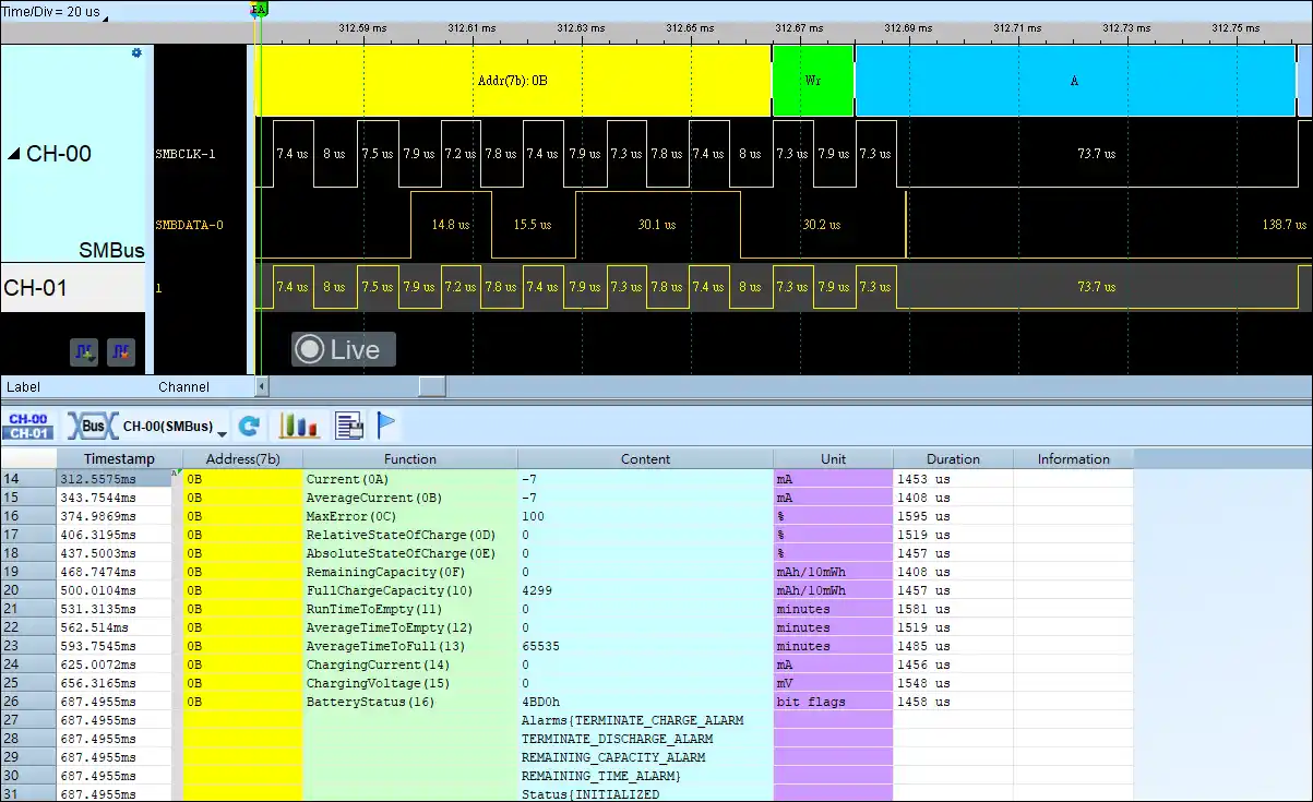
Show SBS (Smart Battery System)
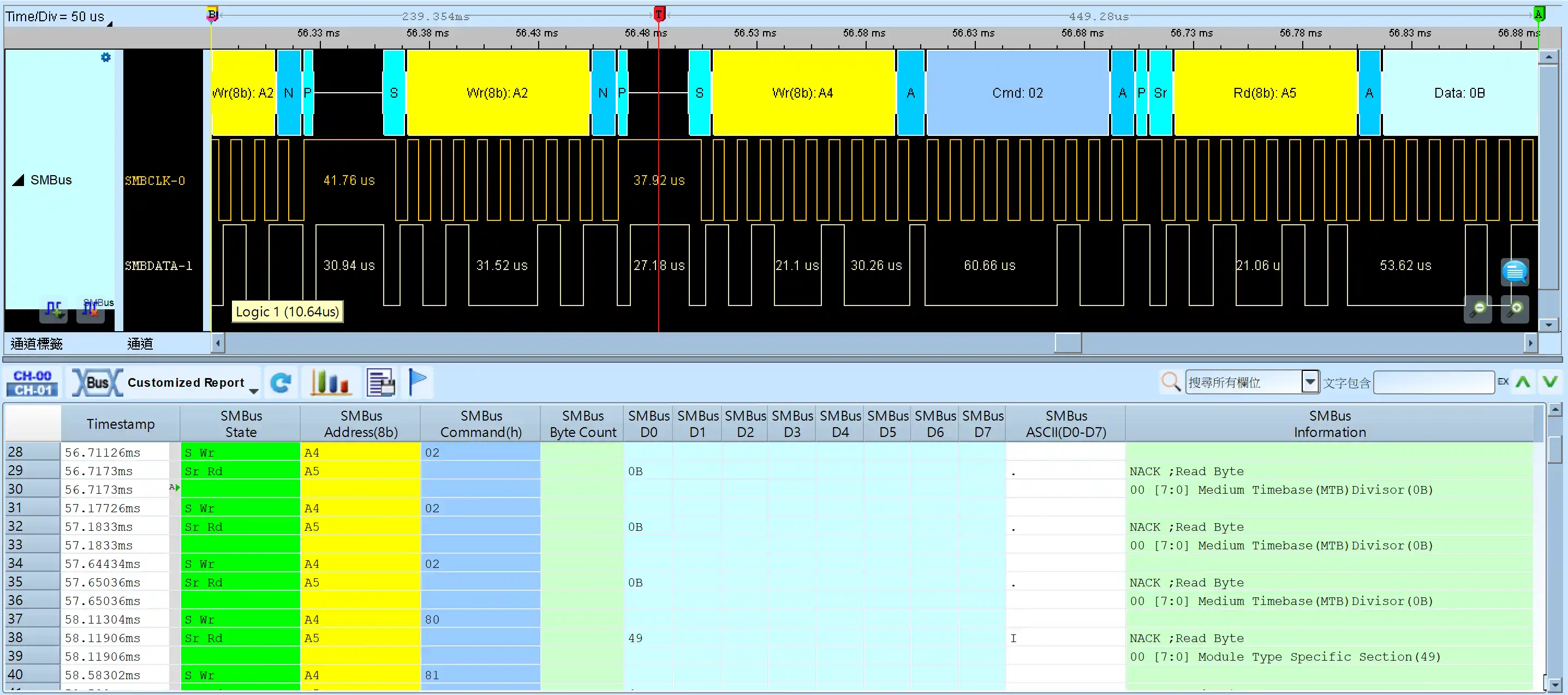
Show SPD (Serial Presence Detect)
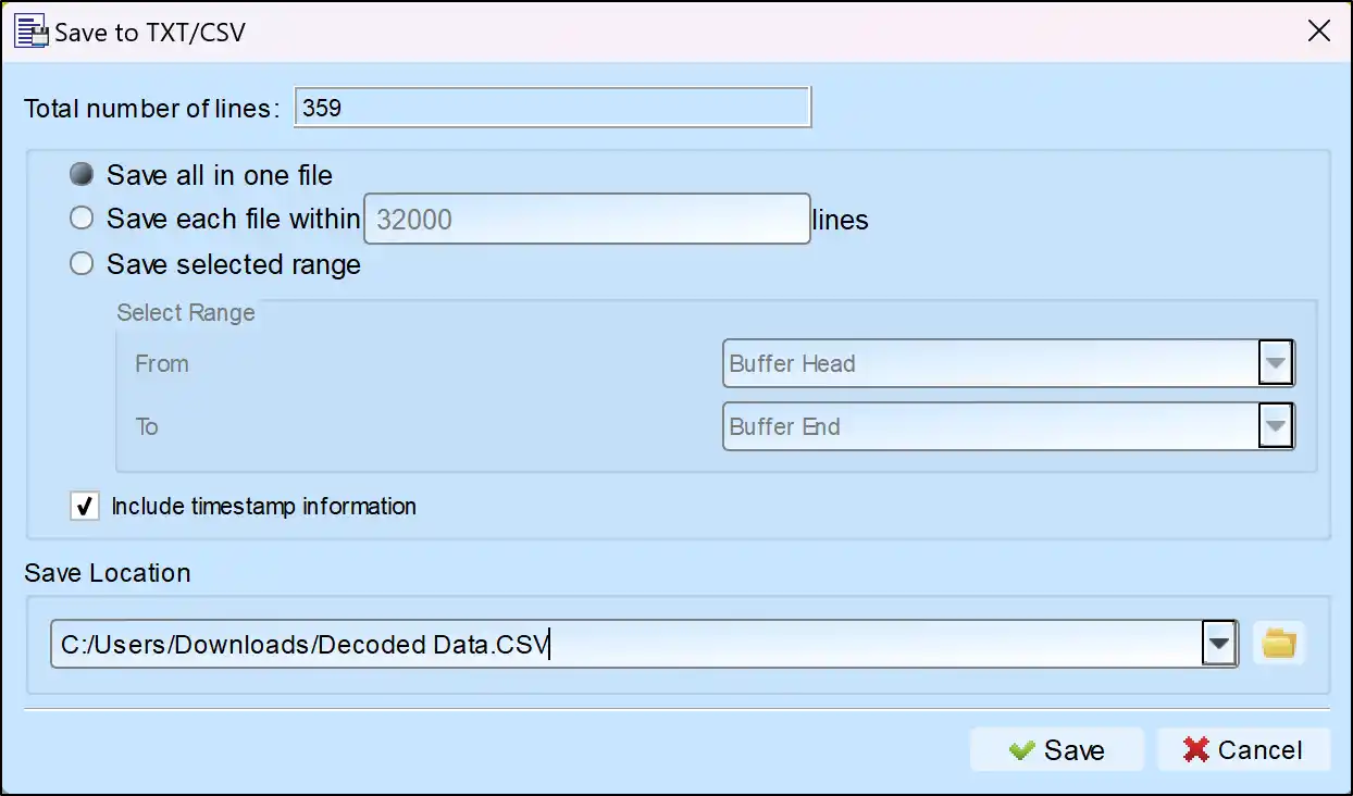
Save as TXT/CSV
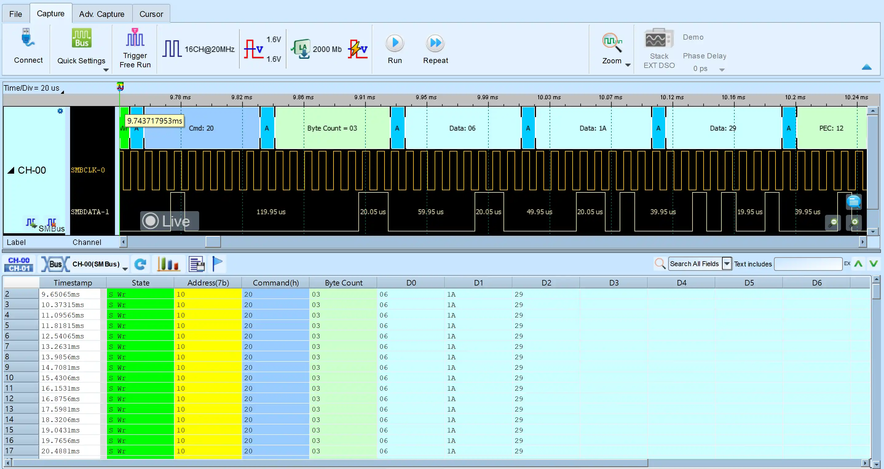
In Logic Analyzer mode, click the icon above the report area to save the decoded data as a TXT/CSV file.

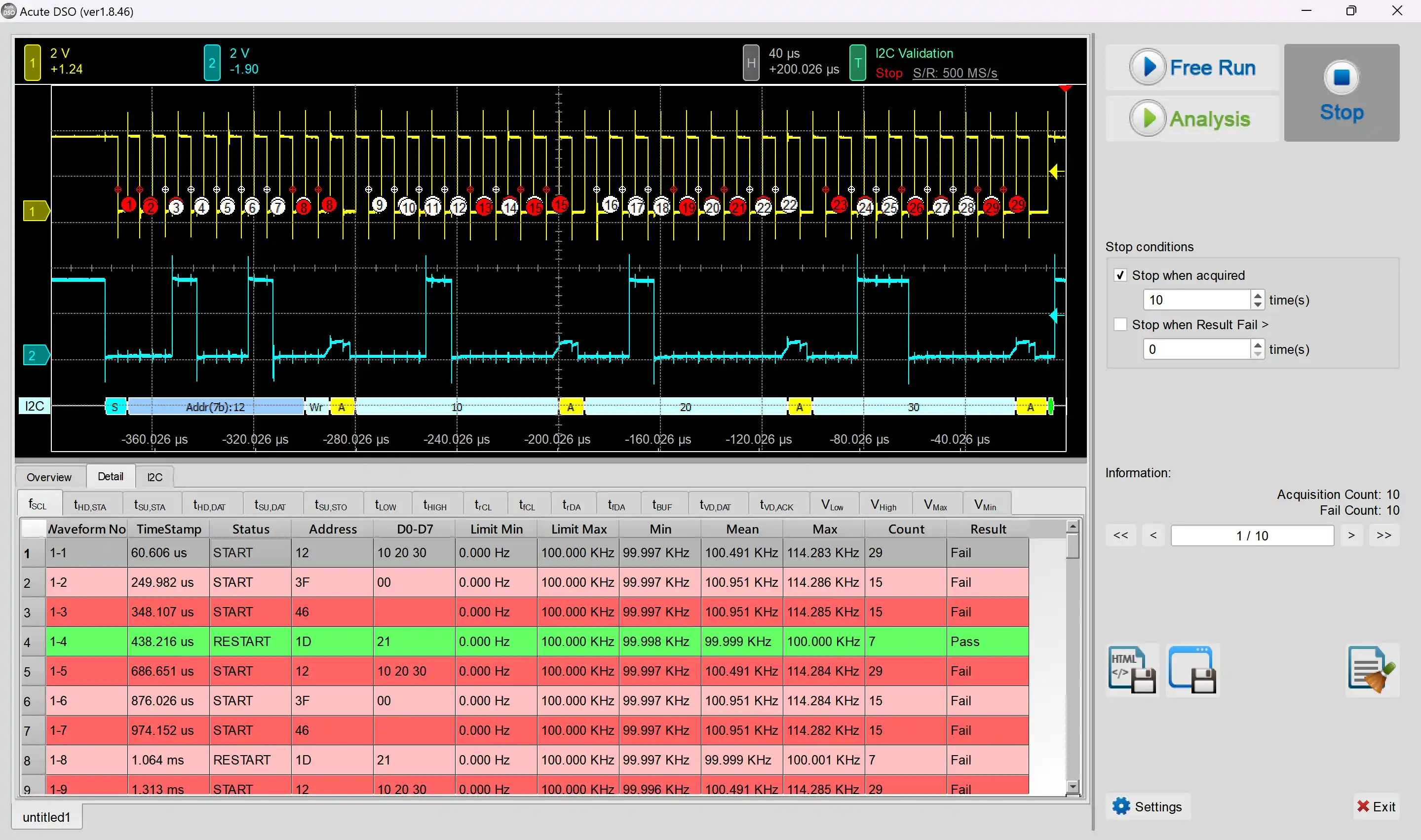
Electrical Validation Solution PDF

SMBus Decoding Setup Steps
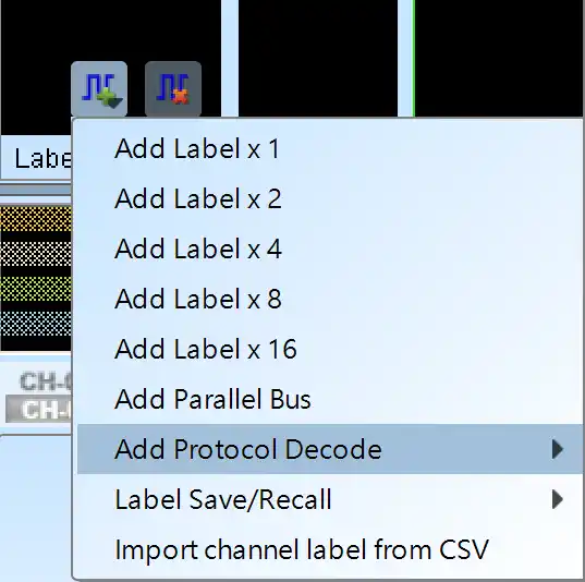
1. Click Quick Settings or Add Protocol Decode to select a protocol for logic analyzer capture.
2. Select SMBus for decoding.
3. If you use Quick Settings, the system will recommend configurations for trigger type, sampling rate, voltage threshold, and channel settings.
4. Click the icon to access the Decode Settings screen.

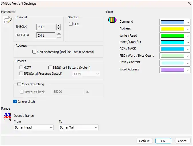
Decode Settings
Channel
SMBCLK: Clock for SMBus data transmission.
SMBDATA: Data for SMBus data transmission.
Startup: Check whether to use PEC analysis.
Address: Show 8-bit addressing (include 7-bit addressing and 1-bit R/W).
Devices
MCTP: Show SMBus analysis in report area.
Show SBS (Smart Battery System): Show the Smart Battery System: voltage, electric current and the manufacturer.
Show SPD(Serial Presence Detect):Report window show the configuration of memory module(DDR3, DDR2, DDR, SPD SDRAM) in EEPROM.
Ignore glitch: Ignore the glitch caused by slow transitions during analysis.
SMBus Decoding Examples