Serial NOR Flash (Single, Dual, Quad, Octal mode)
Single, Dual, Quad NOR Flash
1. Supported Models: TL4234B, MSO2216B, MSO3124H, MSO3124V, LA4068B, LA4136B, BF7264 Pro with LA option
2. Recommended Model: TL4234B
3. Supported Vendors: Atmel, Boya, Dosilicon, ESMT (EON), FMSH, GaintTec, GigaDevice, Infineon, ISSI, Macronix, Microchip (SST), Micron, NOR-MEM, Puyasemi, Spansion, ST, UCUN, Winbond, XMC, XTX, Zbit.

Octal NOR Flash Decode
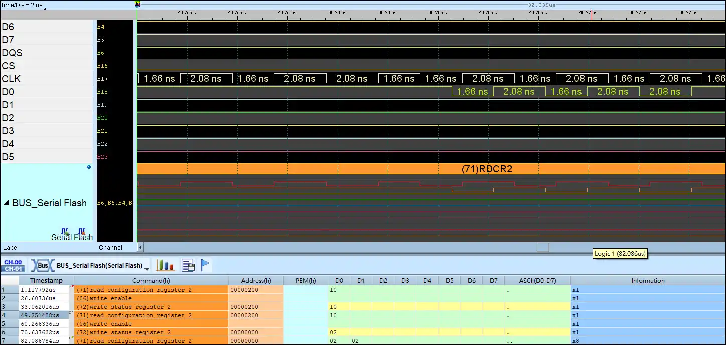
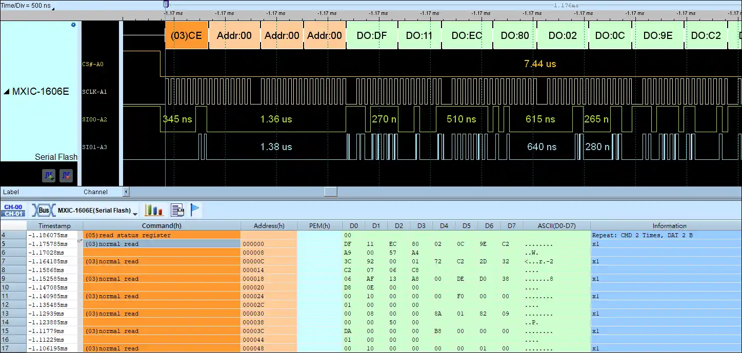
Duel NOR Flash Decode
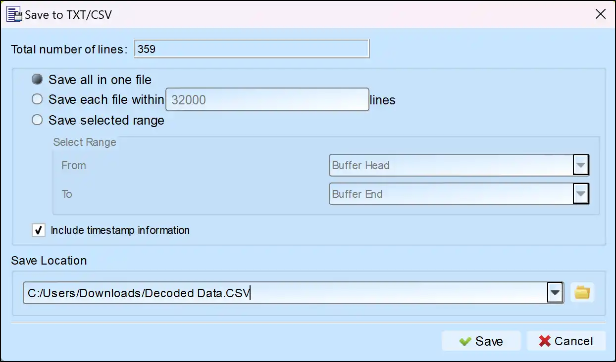
Save as TXT/CSV
In Logic Analyzer mode, click the icon above the report area to save the decoded data as a TXT/CSV file.

Serial Flash Decoding Setup Steps
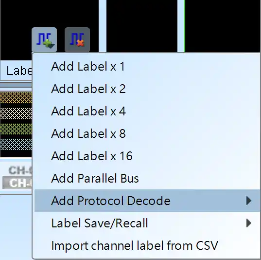
1. Click Quick Settings or Add Protocol Decode to select a protocol for logic analyzer capture.
2. Select Serial Flash for decoding.
3. If you use Quick Settings, the system will recommend configurations for trigger type, sampling rate, voltage threshold, and channel settings.
4. Click the icon to access the Decode Settings screen.

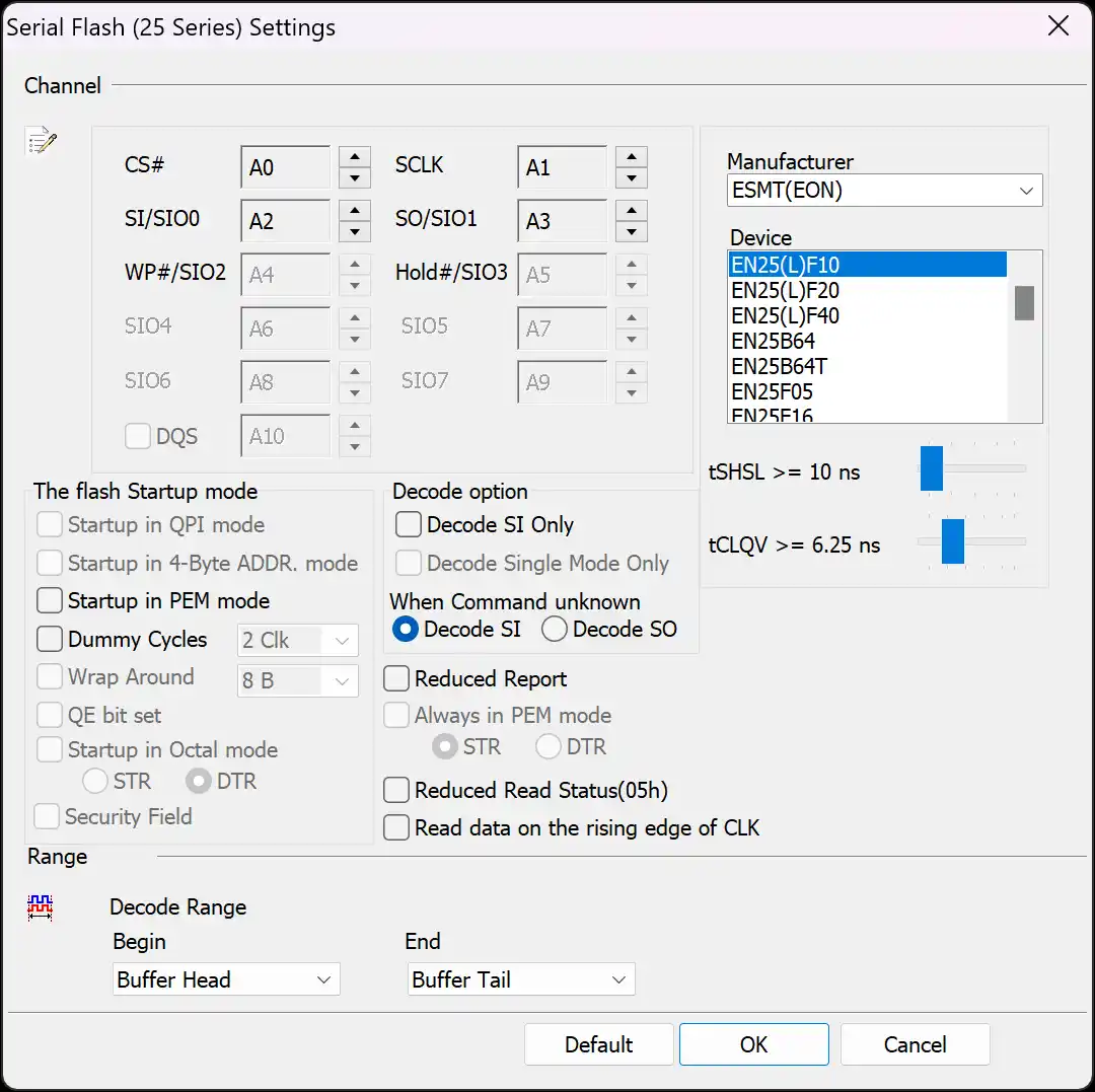
Decode Settings
Channel: Show the selected channels (CH0 – CH5)
Manufacturer/Device: Select the Serial Flash device type, tCLQV and tSHSL.
QPI mode: Quad Peripheral Interface Mode / Quad SPI Mode
4-Byte mode: 4-Byte Address Mode
PEM mode: Performance Enhance Mode
Dummy Cycles: Clock buffers between read command and data.
Wrap Around: Wrap number
QE bit: Enable or disable the QPI mode.
Decode SI Only: Single mode, 3-wire → CS#, SCLK, SI.
Decode Single Mode Only: Single mode, 4-wire → CS, Clock, SI, SO.
The LA viewer will choose 4-wire or 6-wire to analyze according to the Serial Flash device type.
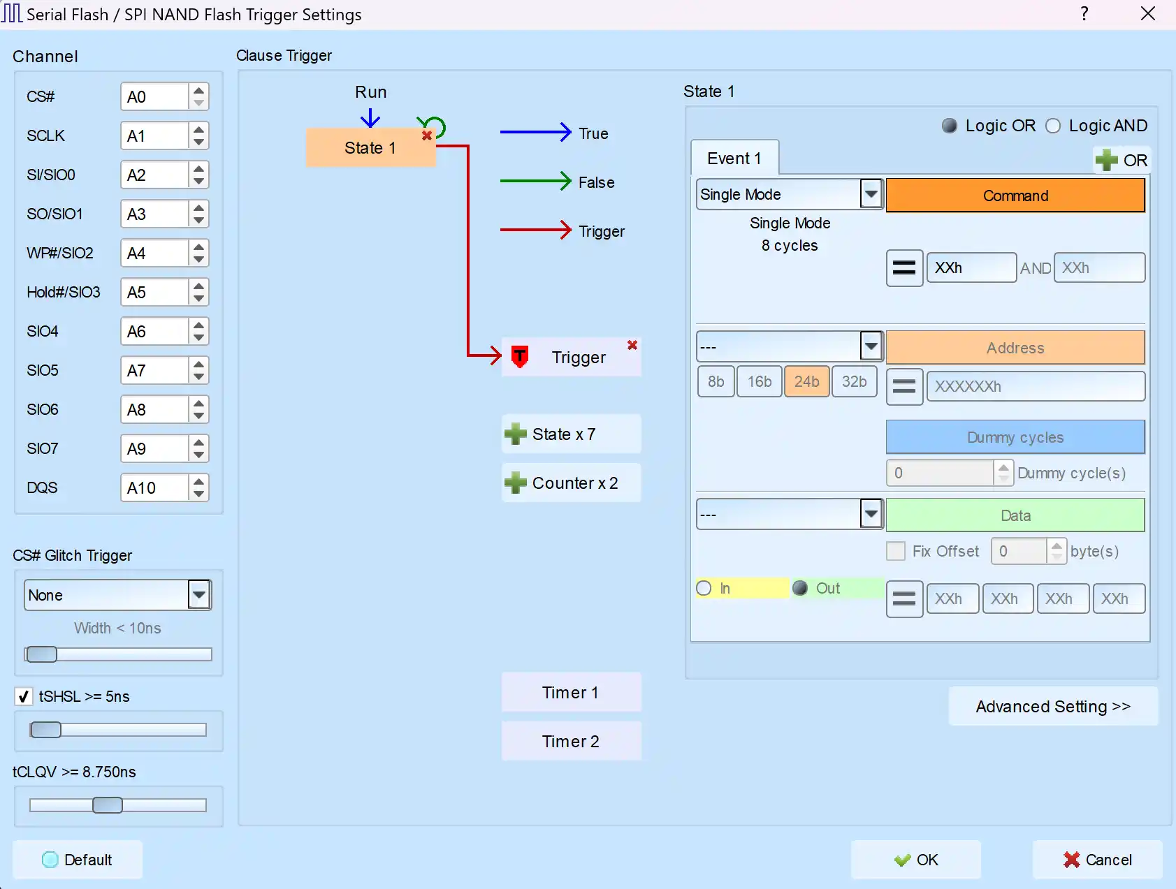
Trigger Settings
Channel: Select channels.
CS# Glitch Trigger: Trigger the glitch on CS# channel.
tSHSL / tCLQV: Set tSHSL / tCLQV.
Clause Trigger: Please reference Clause Trigger chapter.
State: Show the details of trigger condition in every state as left side; typing or selecting the trigger values in the Command, Address and Data fields, default value is XX means “don’t care”.
Provided the Single / Dual / Quad / Octal mode
Serial Flash (SPI Flash) Decoding Example