
I²C

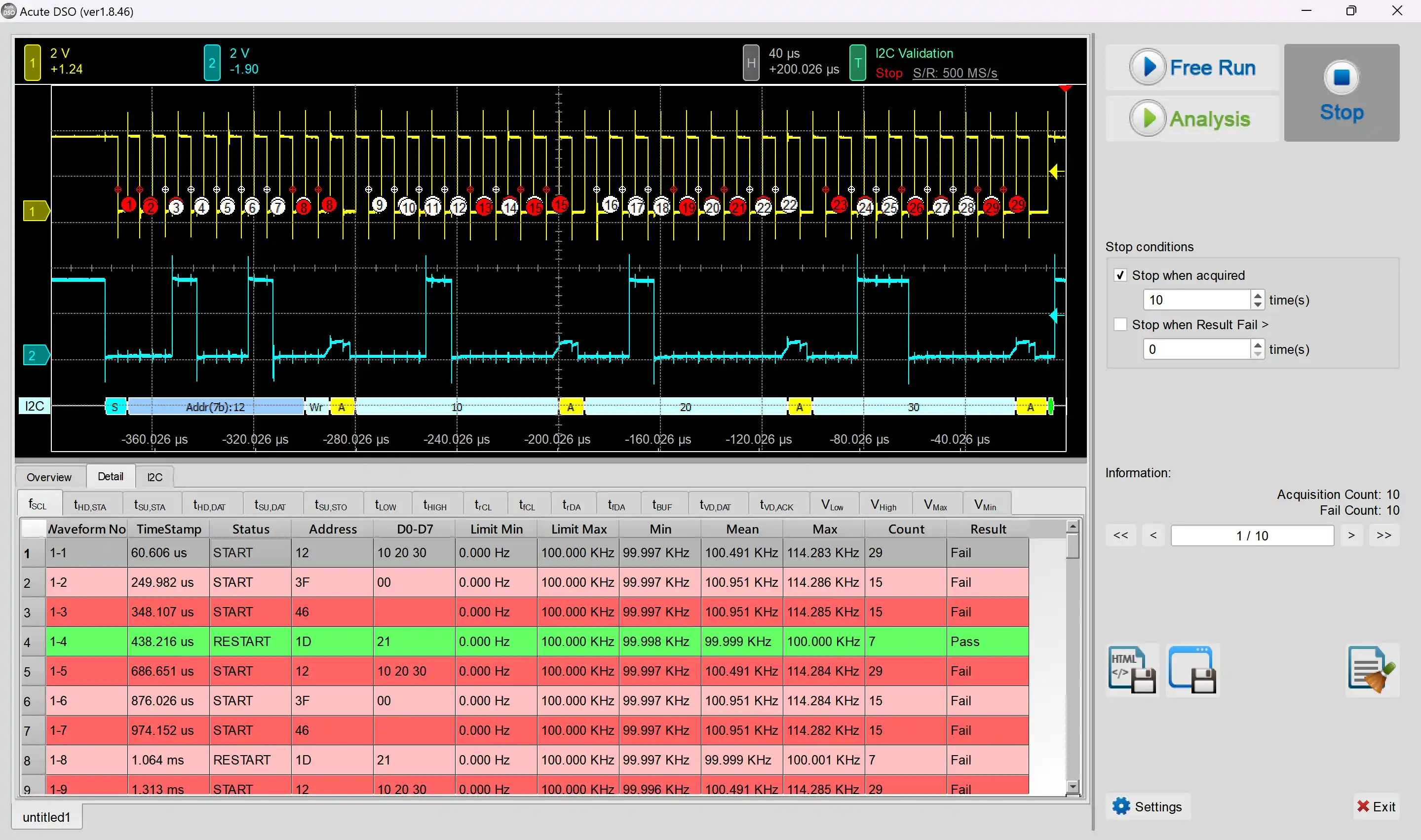
Electrical Validation Solution PDF

I²C Decodes / Waveforms
Effectively solves the problem of slow signal transitions during actual measurements of I²C signals, making it difficult to measure. Able to stack with a DSO to form as an MSO.
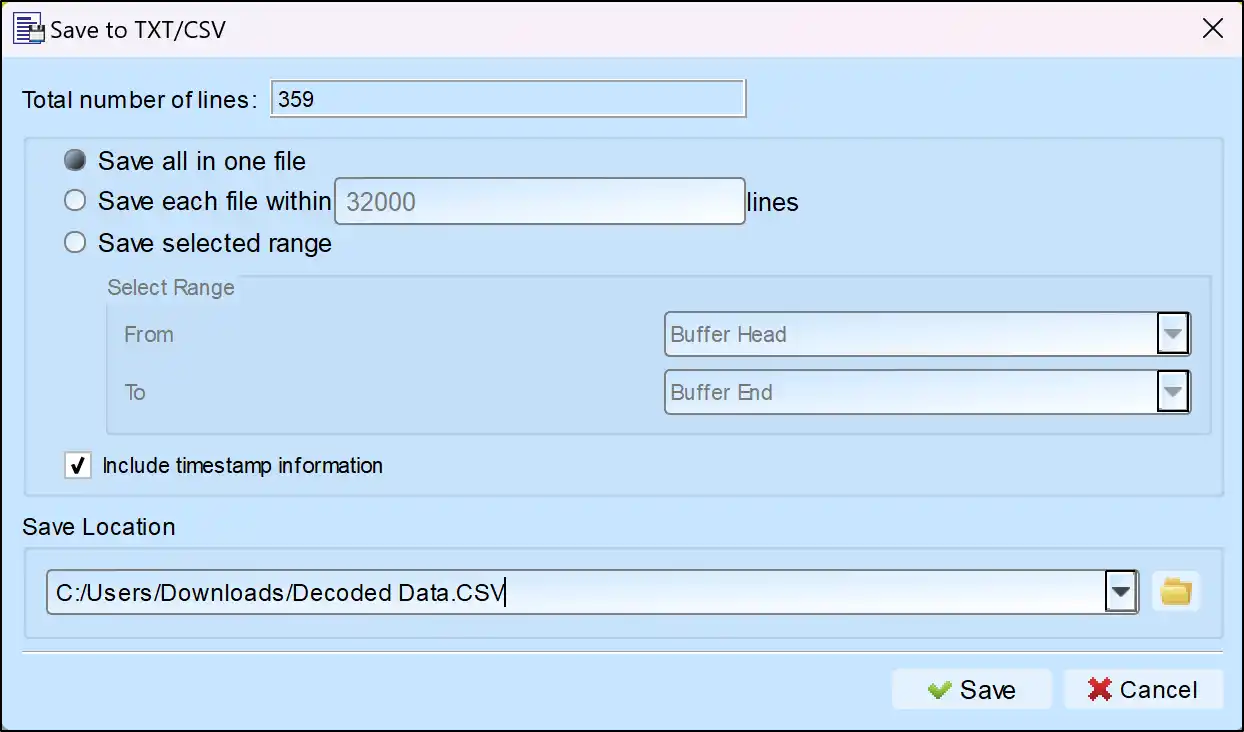
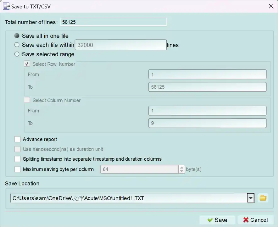
Save as TXT/CSV
In Logic Analyzer mode, click the icon above the report area to save the decoded data as a TXT/CSV file.

I2C Decoding Setup Steps
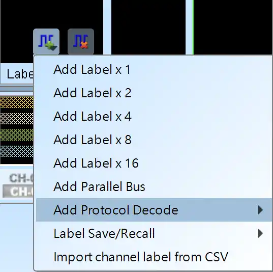
1. Click Quick Settings or Add Protocol Decode to select a protocol for logic analyzer capture.
2. Select I2C for decoding.
3. If you use Quick Settings, the system will recommend configurations for trigger type, sampling rate, voltage threshold, and channel settings.
4. Click the icon to access the Decode Settings screen.

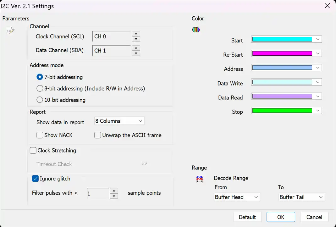
Decode Settings
Channel: Specify the Logic Analyzer channel number connected to each signal end on the device under test.
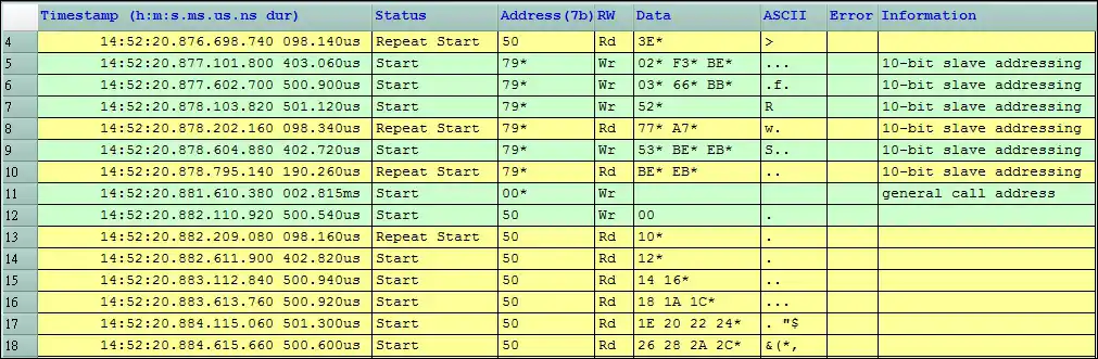
Address Mode: Select between 7-bit or 10-bit addressing.
7-bit Addressing: Display using 7-bit addressing.
8-bit Addressing (Including R/W): Display using 8-bit addressing, including 7-bit address and 1-bit Read/Write (Rd/Wr).
10-bit Addressing: Display using 10-bit addressing.
Report: Choose between 8-column or 16-column data in the report window.
Ignore Glitch: Ignore glitches caused by slow transitions.
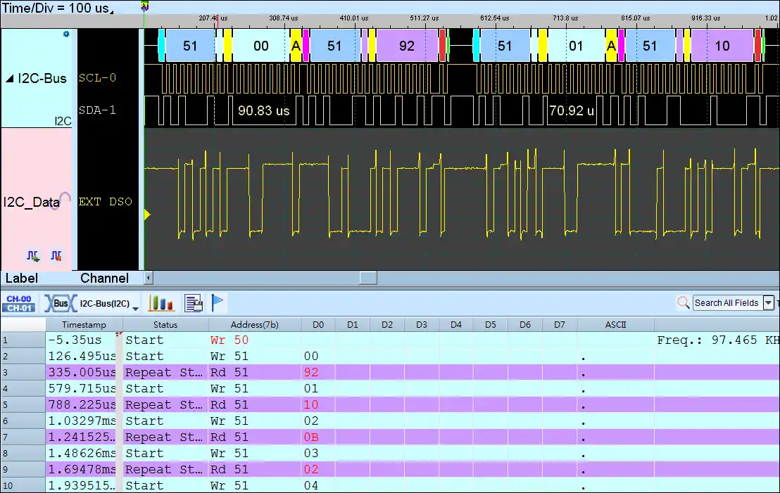
I²C Protocol Analyzer Report
A user-friendly software interface with just 3 simple steps to start capturing bus data. Designed with USB 3.0 for fast data transfer, and when used with a 64-bit operating system, it fully leverages the PC’s memory, enabling long-term data capture of serial bus protocols, ranging from hours to days. When the simultaneous waveform capture option is enabled, users can view both protocol data and the corresponding digital waveforms in real time, making it an efficient data acquisition (DAQ) solution.
Save as TXT/CSV
In Protocol Analyzer mode, click the icon above the report area to save the decoded data as a TXT/CSV file.

I²C Decoding Examples