
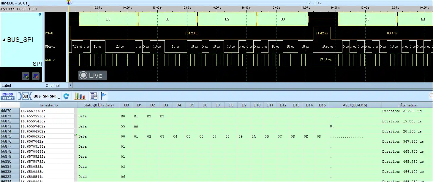
SPI


SPI Decode
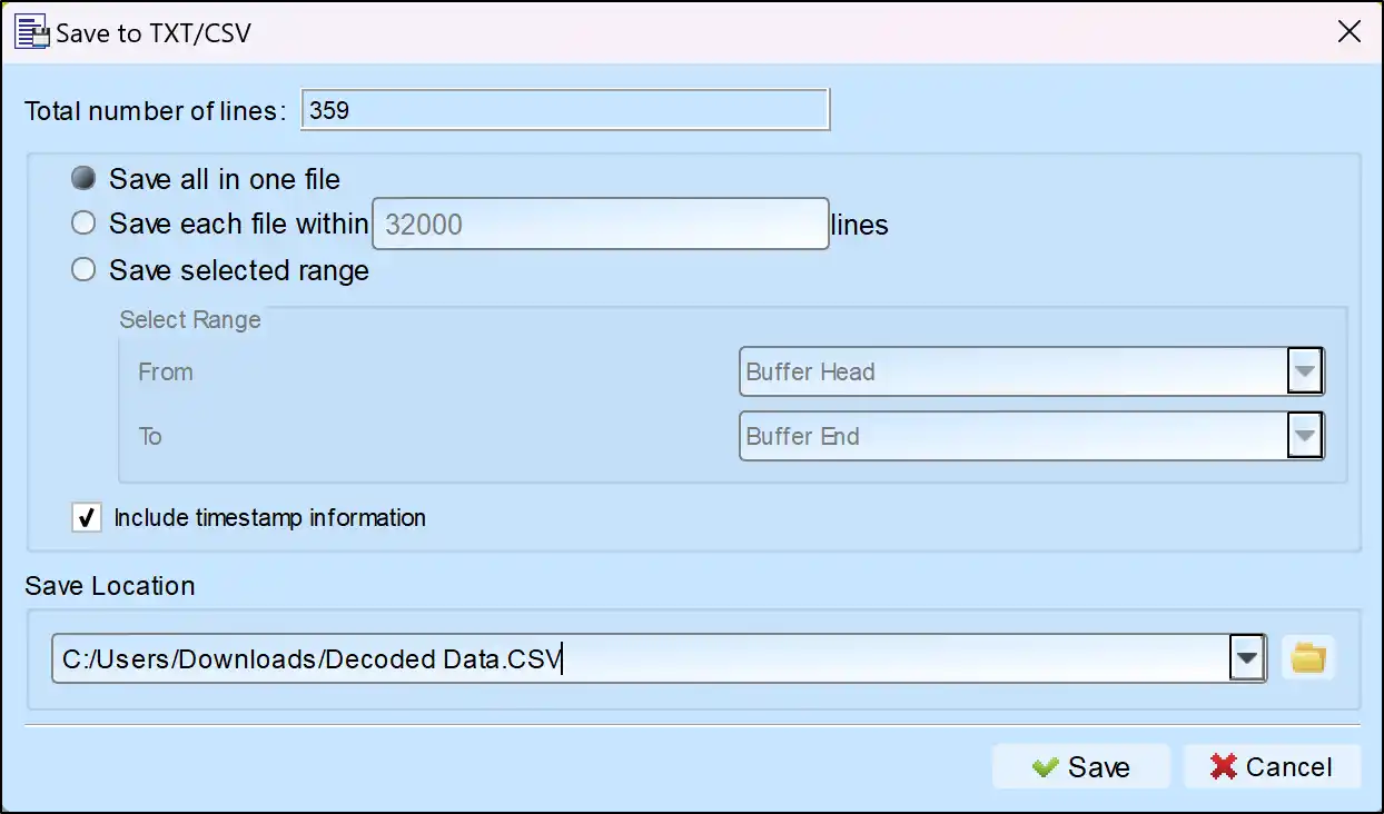
Save as TXT/CSV
In Logic Analyzer mode, click the icon above the report area to save the decoded data as a TXT/CSV file.

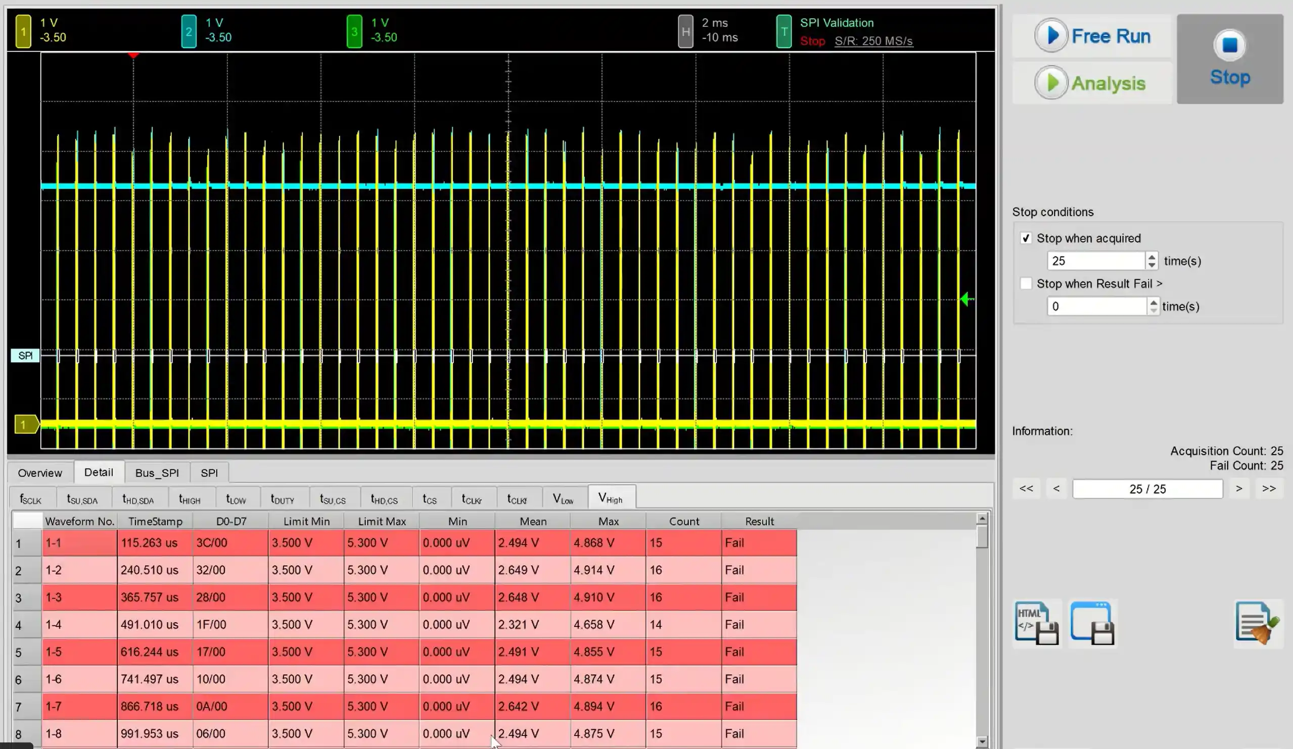
Electrical Validation Solution PDF

SPI Decoding Setup Steps
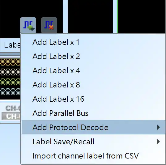
1. Click Quick Settings or Add Protocol Decode to select a protocol for logic analyzer capture.
2. Select SPI for decoding.
3. If you use Quick Settings, the system will recommend configurations for trigger type, sampling rate, voltage threshold, and channel settings.
4. Click the icon to access the Decode Settings screen.


Decode Settings
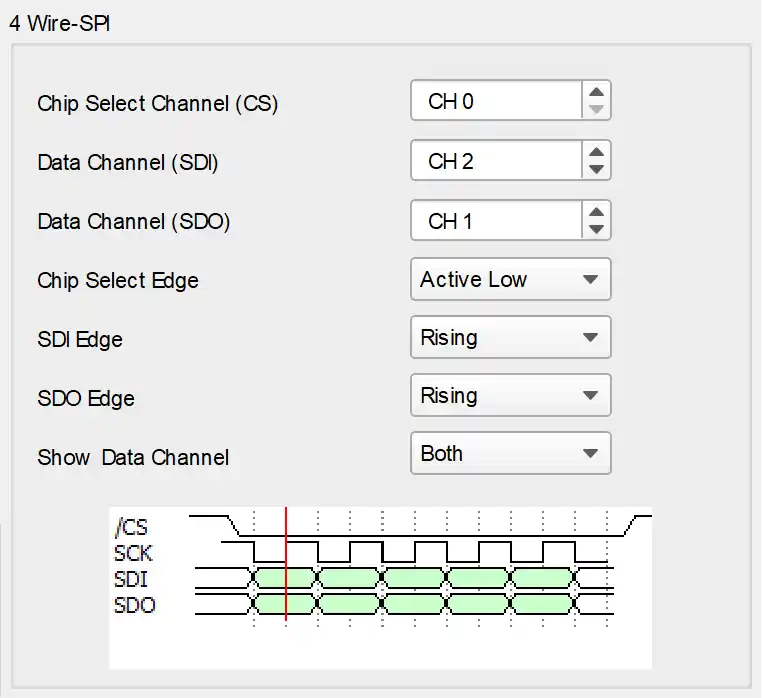
Type: Select the SPI category, the default is 3-wire-SPI, the following 4 types are included
4-wire-SPI→use SCK, CS, SDI or SDO
3-wire-SPI→use SCK, CS, SDA
3-wire-SPI (not using Chip select) → using SCK, SDI, SDO
2-wire-SPI (not using Chip select) → using SCK, SDA
Bit Order
You can set MSB first or LSB first when parsing SPI data. The default is MSB first.
Word Size
You can set the size of each Data word in bits. When SPI parses, this value will be used as the number of bits to collect each Data word. The minimum value is 4 and the maximum value is 40. The default value is 8.
Report
Show Idle state in the report: When SPI is used in an application, there may be Idle states appearing each time data is fetched. For convenient data inspection, you can configure the report window not to display Idle status. The default is to display Idle status.
Show data in report (Column): You can set the display mode for consecutive SPI data, choosing between 1 to 16 columns displayed in the report window. The default is 16 columns, and on the right side of the report window, you can see the result in ASCII encoding.
4-wire SPI → using SCK, CS, SDI, or SDO
You can individually set the trigger edges for CS, SDI, and SDO. CS is default set as Active Low, and SDI/SDO is default set as Active High. Since SDI and SDO data appear simultaneously, you can choose within the data display channel to show only SDI, only SDO, or both, with the default setting being Both.
3-wire SPI → using SCK, CS, SDA
In the 3-wire mode with Chip Select, only one data channel is needed (which can be either SDI or SDO). You can individually set the trigger edges for CS and Data. CS is default set as Active Low, and Data is default set as Active High. In typical applications, the data channel is a single-line unidirectional method for transmitting data.
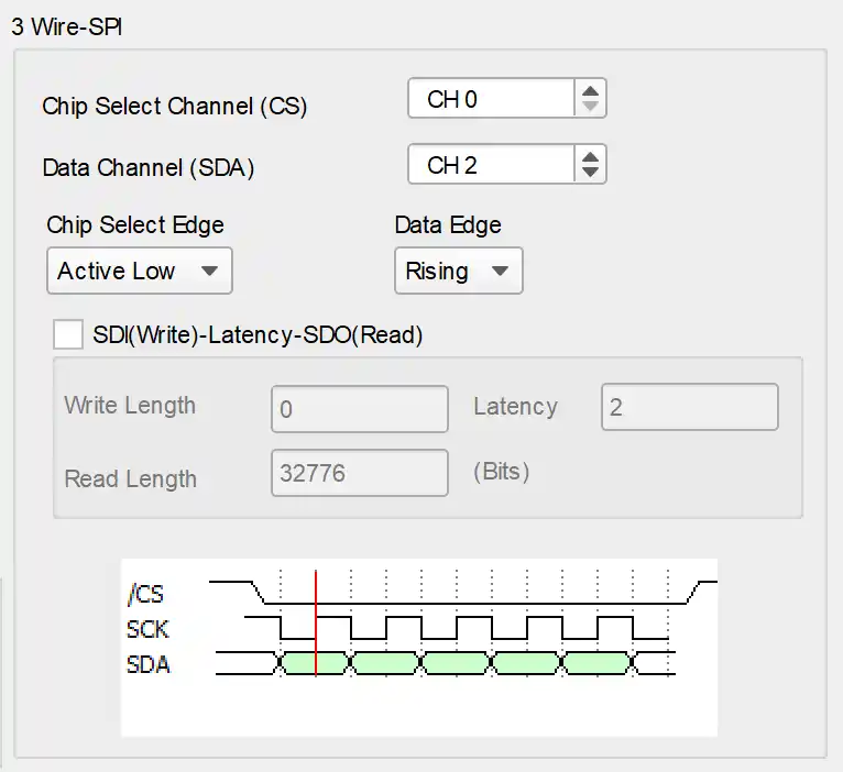
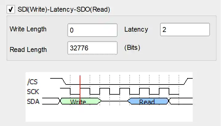
We also provide a single-line bidirectional transmission mode.
You only need to check "SDI(Write)-Latency-SDO(Read)" to configure the bit number for bidirectional transmission. From the Master"s perspective, the write length is the number of bits that the Master puts into the data channel, with a minimum of 1. The wait for Slave processing is the number of bits, with a minimum of 0. Then, data is collected based on the read length, with a minimum of 1. The maximum value for these three parameter settings is 65535.
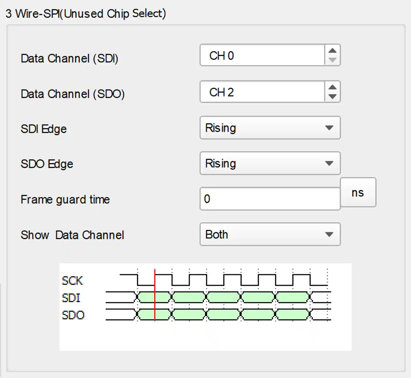
3 Wire-SPI (Unused Chip Select) → SCK, SDI, SDO
Because CS is not used, it is necessary to set the Idle time of SCK as the separation time between frames. In the 3-wire mode without using Chip select, you need to configure the channel where SDI/SDO is located and their trigger edges, with the default being Active High. Set the waiting time for Clock Idle as the separation time for frames. Since SDI and SDO data appear simultaneously, you can choose within the data display channel to show only SDI, only SDO, or both, with the default setting being Both.
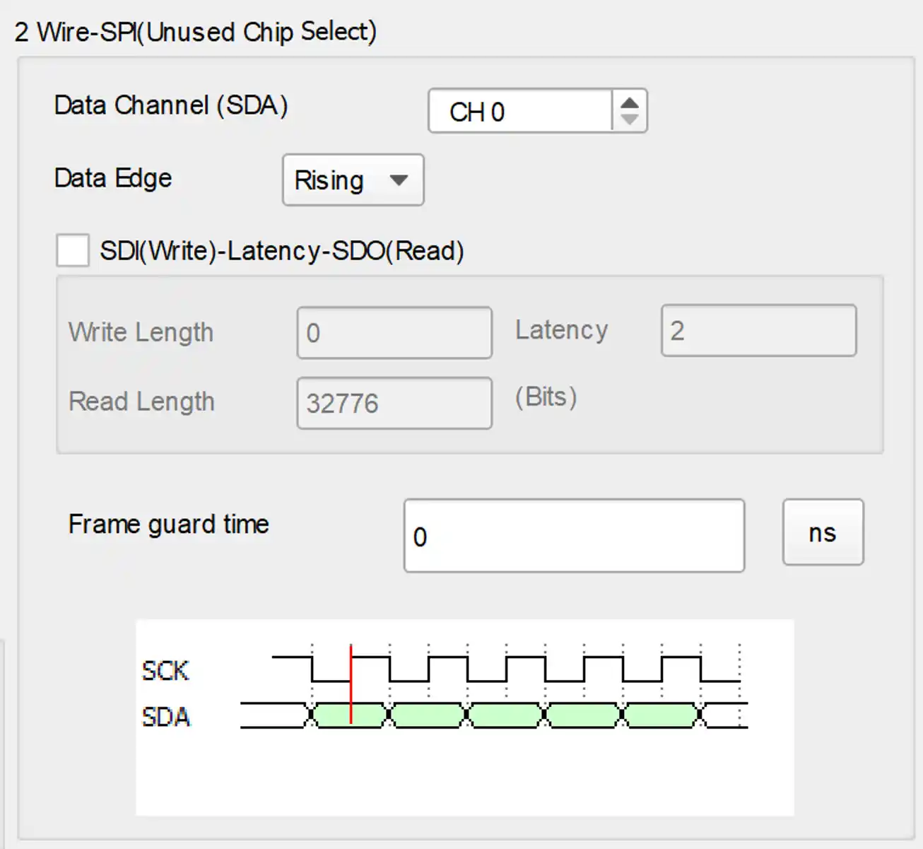
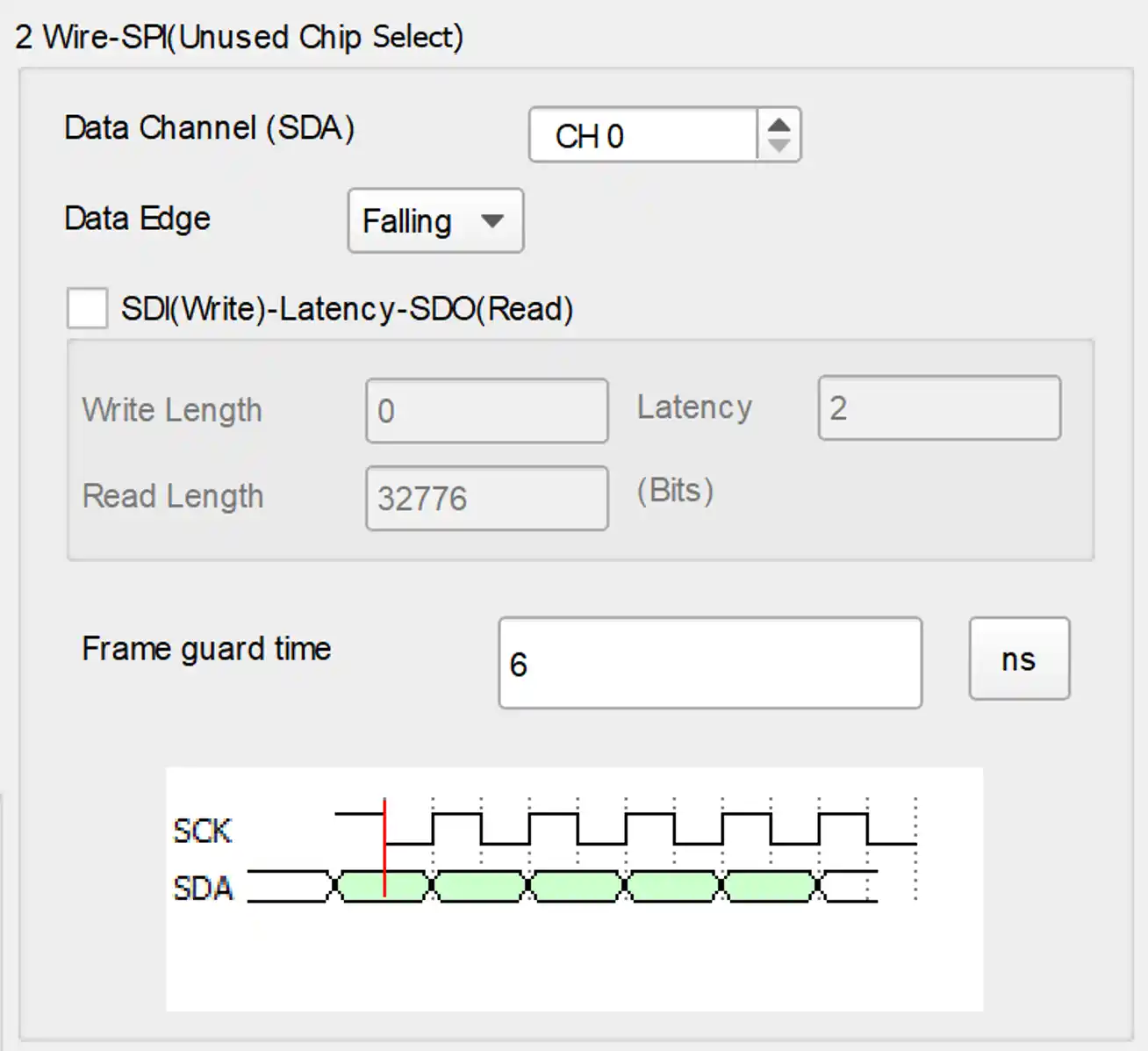
2 Wire-SPI (Unused Chip Select) → SCK, SDA
Since CS is not used, it is necessary to set the Idle time of SCK as the separation time between frames. In the 2-wire mode without using Chip select, you need to configure the channel where the data is located and its trigger edge, with the default being Active High. Set the waiting time for Clock Idle as the separation time for frames. In typical applications, the data channel is a single-line unidirectional method for transmitting data.
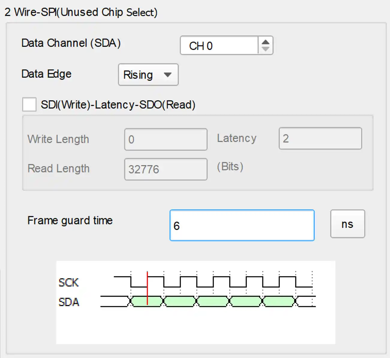
If the chip select is not used and the interval between frames is not 0. You can set the interval as 6us, any data bit higher than 6us will be seen as Idle.

If the chip slave is not used and the interval between frames is 0. You can see the data continuous as the dialog below.

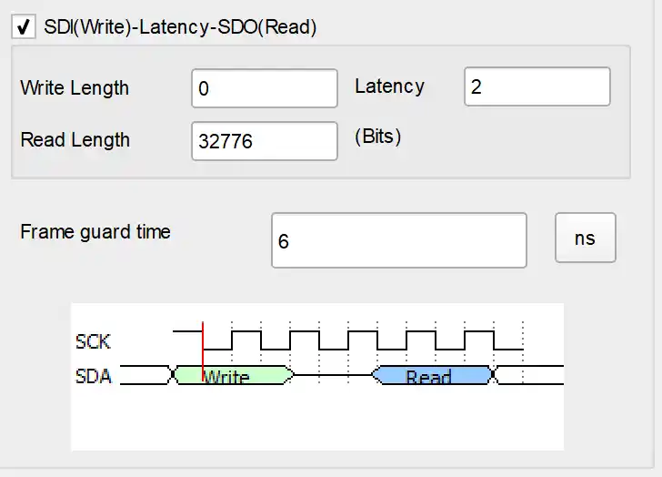
We also offer bi-direction mode.
Check the "SDI(Write)-Latency-SDO(Read)" to set the bit numbers for the 3 columns; Write and Read (1~65535), Latency (0~65535).
SPI Decoding Examples