
RS-232
UART(RS232) Decode
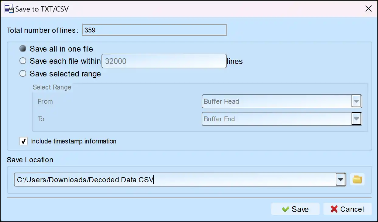
Save as TXT/CSV
In Logic Analyzer mode, click the icon above the report area to save the decoded data as a TXT/CSV file.

Electrical Validation Solution PDF

UART(RS232) Decoding Setup Steps
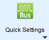
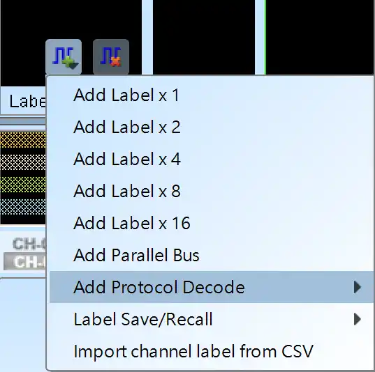
1. Click Quick Settings or Add Protocol Decode to select a protocol for logic analyzer capture.
2. Select UART(RS232) for decoding.
3. If you use Quick Settings, the system will recommend configurations for trigger type, sampling rate, voltage threshold, and channel settings.
4. Click the icon to access the Decode Settings screen.

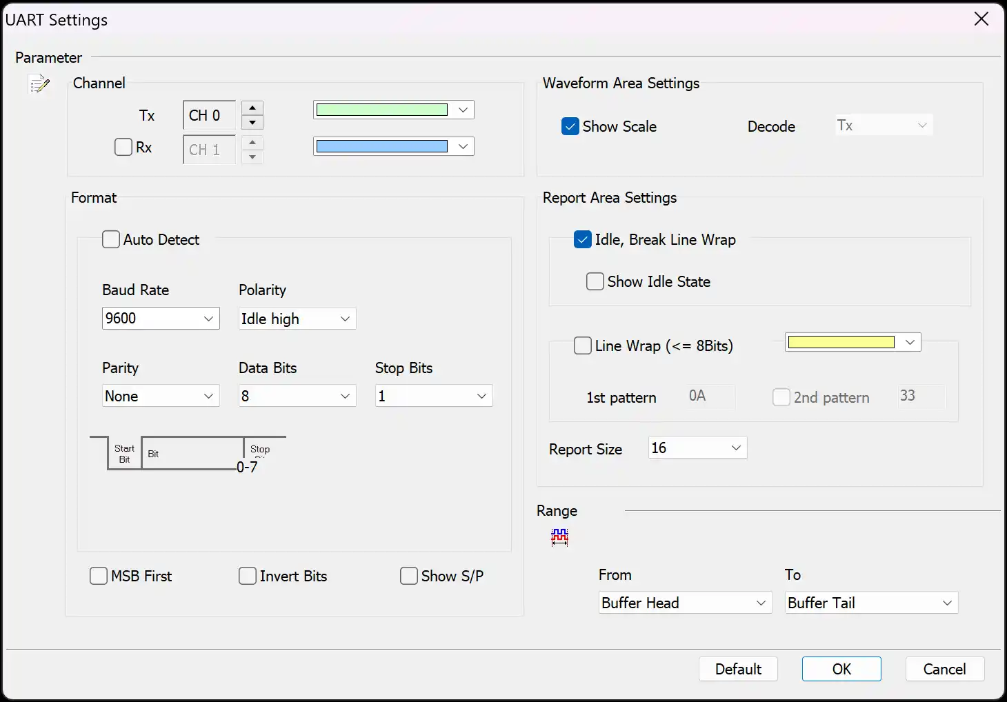
Decode Settings
Channel:
- Tx: Assign the Tx signal pin to the corresponding channel number of the logic analyzer.
- Rx: Assign the Rx signal pin to the corresponding channel number of the logic analyzer. Enabled when selected.
Format:
- Auto: Automatically detect the settings for the following options. Enabled when selected.
- Baud Rate: The data transmission speed, measured in bits per second (bps). The supported range is 110 to 2M bps.
- Polarity: Includes Idle High and Idle Low formats.
- Parity: Includes N - None Parity (No parity bit), O - Odd Parity, and E - Even Parity.
- Data Bits: Can be set between 4 to 16 bits.
- Stop Bits: Can be set to 1, 1.5, 2, 2.5, 3, 3.5, 4, or 4.5 bits.
- MSB First: When selected, the Most Significant Bit (MSB) comes after the Start Bit. When not selected, the Least Significant Bit (LSB) is used.
- Invert Bits: Reverses High and Low levels. Enabled when selected.
- Show S/P: Displays Start and Stop in the waveform area. Enabled when selected.
Waveform Area Settings:
- Decode: Select whether to display the Rx or Tx decoding results in the waveform area. The Rx option is only effective when the Rx channel is enabled.
- Show Scale: Displays the scale in the waveform area. Enabled when selected.
Report Area Settings (enabled when selected):
- Show Idle State: Displays Unknown and Idle states in the report window.
- Line Wrap Data: Allows setting two values as the primary order for decoding, making it easier to view analysis results.
- Report Size: Sets the number of Data fields in the report area. Can be set to 16 or 32.
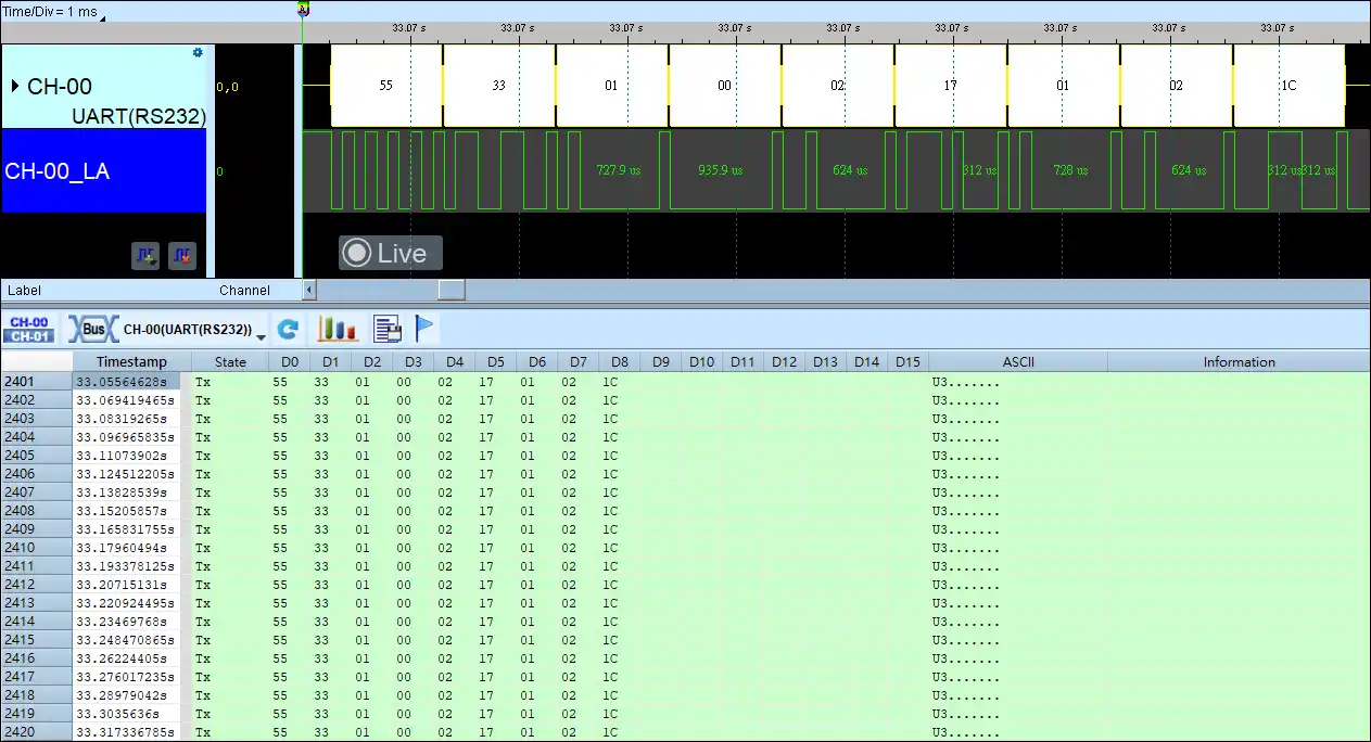
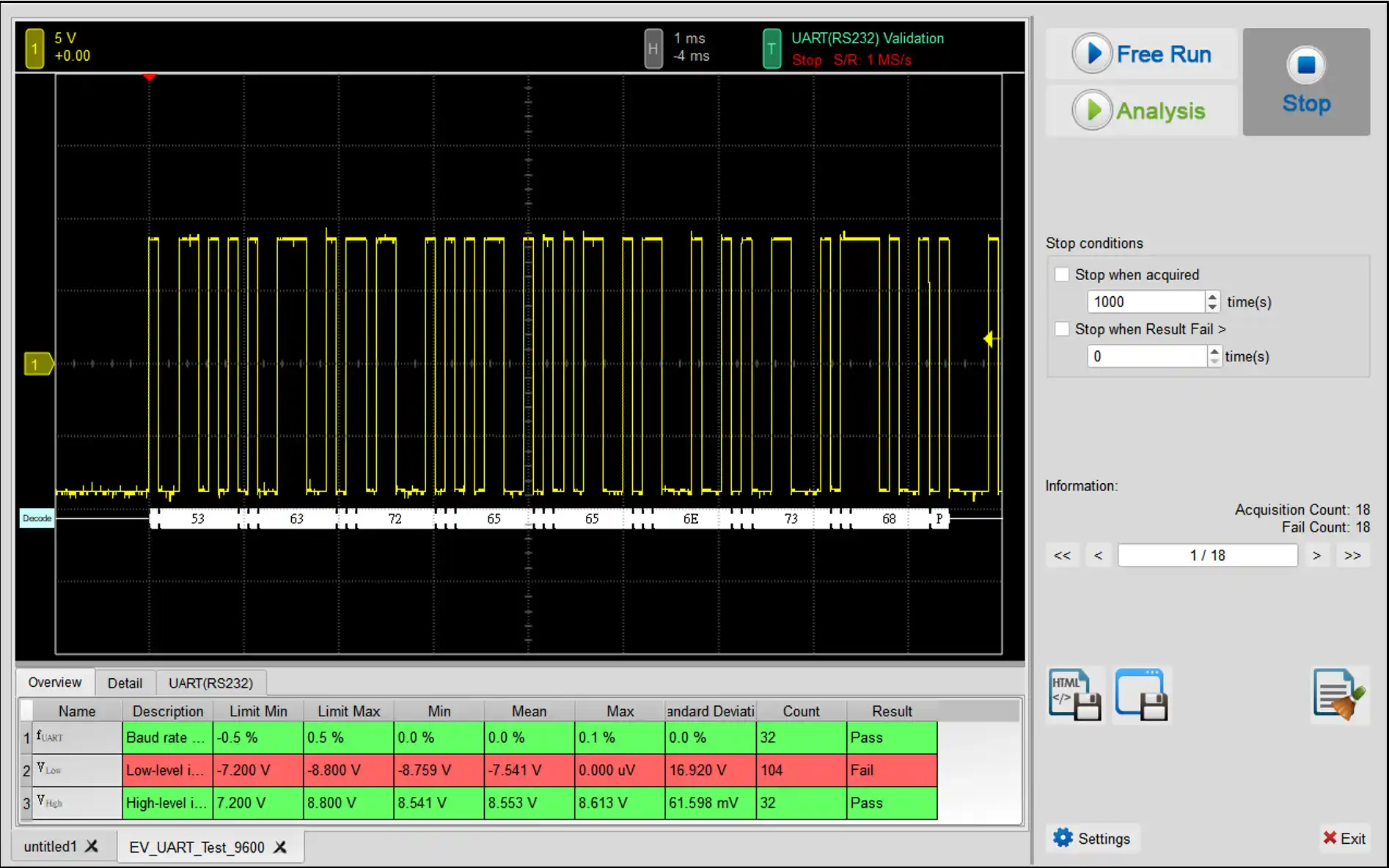
UART Decoding Examples